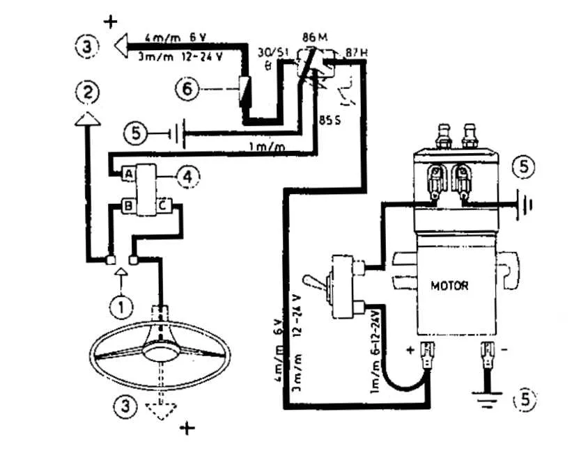
For a reliable installation of your vehicle’s sound system, it’s crucial to use a high-power switch to control the compressor effectively. First, ensure that the main power source is properly fused to protect against short circuits. A dedicated fuse should be installed near the battery to prevent any damage from overcurrent.
Next, connect the control circuit through a heavy-duty switch that can handle the electrical load required by the system. This switch should be positioned inside the cabin for easy access while driving, but far enough from any heat sources to avoid malfunction.
To manage the connection to the compressor, use a high-current solenoid to ensure that the power flow is properly directed. The solenoid should be mounted in a location where it is shielded from moisture and extreme temperatures to prevent rust and corrosion.
When connecting all components, make sure to use appropriately gauged wire that can handle the electrical demands of the system. Thicker wires are recommended for the primary connections, while thinner wires can be used for the triggering mechanisms. Proper insulation is critical to avoid any accidental shorts.
Wiring Setup for High-Decibel Sound System Using a Switch
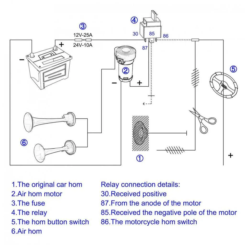
To achieve optimal functionality for a high-decibel sound system, ensure that the setup includes a heavy-duty switch, a power source, and a control system for the sound unit. Start by connecting the positive terminal of the power supply to the switch’s input. From there, link the switch’s output to the power terminal of the sound unit, ensuring proper gauge wires to handle the current.
For safety and efficiency, install a fuse close to the power source. This acts as a safeguard, protecting against any unexpected electrical surges. On the control side, use a secondary low-current switch, such as a button or toggle, to trigger the circuit.
Integration of a secondary component for enhancing power distribution is crucial. It allows the high-current sound unit to function without overwhelming the control switch. This secondary component should be wired between the main switch and the sound unit. Make sure that the component is rated for the appropriate amperage and voltage.
Finally, check all connections for secure fit and insulation. Any loose or exposed wiring could lead to malfunction or risk of short circuits. Once installed, conduct a thorough test of the entire system to confirm that the system operates without issue and the sound unit activates correctly.
Connecting a Loudspeaker to a Switch for Correct Activation

Ensure that the power source is capable of supporting the required voltage for the device. A typical automotive system requires at least 12V to properly operate the system.
- Start by connecting the power input terminal to a fuse to protect the circuit from short circuits or overcurrent.
- Run the wire from the power source to the control mechanism, ensuring a secure connection to the control switch.
- Next, connect the device’s positive terminal to the switched output of the controller, making sure the wire is thick enough to handle the power demand.
- Use a grounding point on the vehicle frame or a dedicated ground wire to complete the circuit for the device’s negative terminal.
Check that all connections are properly insulated to avoid exposure to elements that could cause corrosion or shorts.
- For extra safety, use heat shrink tubing around any exposed metal parts of the wiring to prevent corrosion.
- Double-check all connections for tightness and security, especially at the power and ground terminals.
- Test the system by activating the switch and ensuring the loudspeaker produces sound as intended.
Choosing the Correct Relay and Fuse for Vehicle Sound Systems

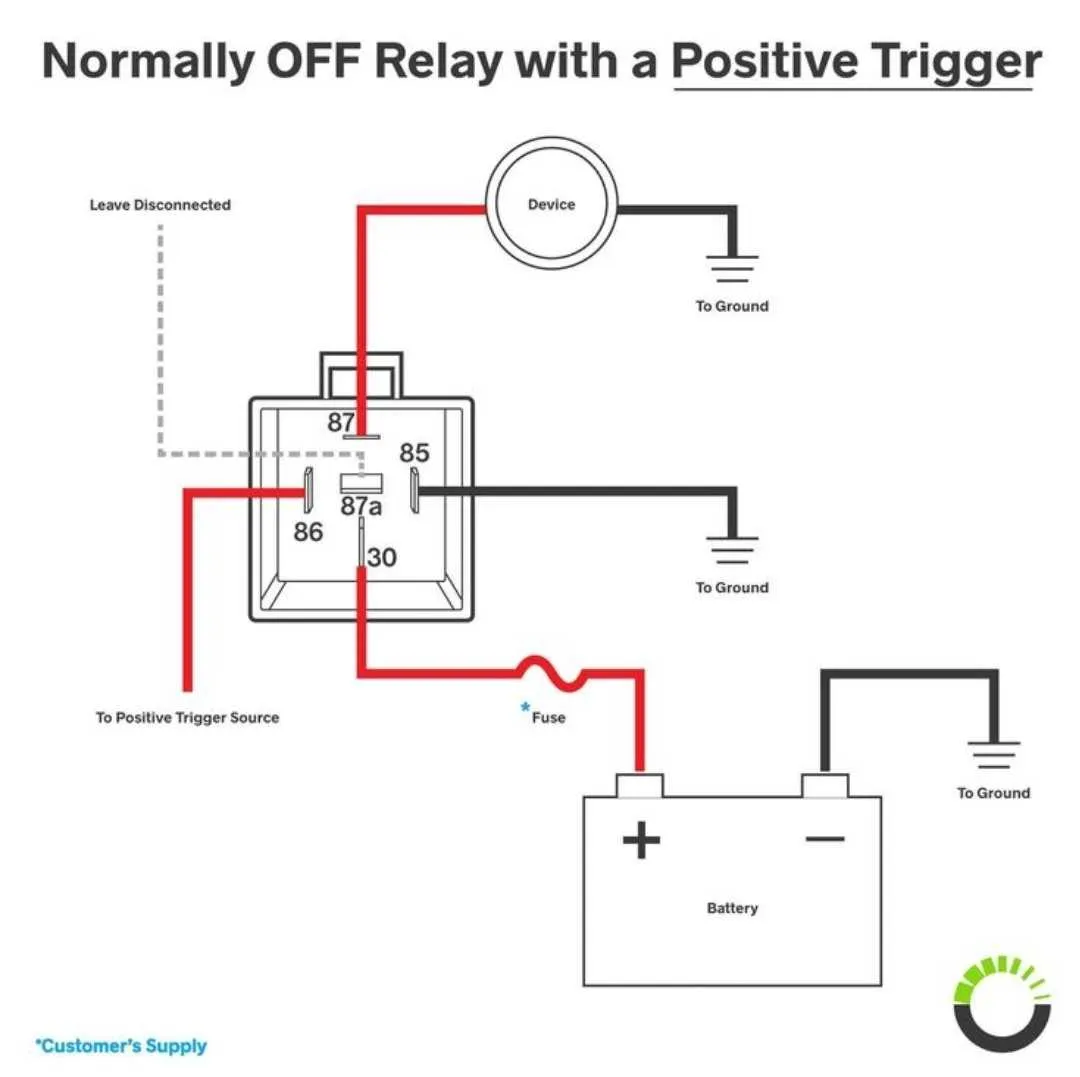
For optimal performance of your vehicle’s sound system, select a 12V automotive relay rated for at least the system’s peak current demand. Typically, systems require a relay that can handle 30A to 40A for proper operation, ensuring the switch doesn’t overheat. Ensure that the relay has a low coil resistance and is designed for continuous duty.
The fuse size should match the system’s peak current draw but be slightly higher to avoid unnecessary interruptions. A 40A fuse is commonly used for systems drawing up to 30A. It’s crucial to choose a fuse that will blow in case of an overload or short circuit to protect your vehicle’s electrical components.
Always consider the voltage rating of the fuse and relay. For 12V systems, 32V rated components are often the best choice as they provide a safety margin for voltage spikes and fluctuations.
When installing the fuse, place it as close to the power source as possible to limit the risk of damage to the wiring. The wire gauge should be chosen based on the current draw, typically 10 AWG or thicker for high-power systems.
Lastly, ensure the fuse and relay are compatible with your system’s total load and intended use, such as for brief bursts of high energy or continuous operation, to avoid premature wear or failure of the components.
Step-by-Step Guide for Installing the Sound Signal Circuit
Begin by disconnecting the battery to avoid accidental short circuits. Use a proper gauge wire (typically 12-14 AWG) for the connection from the power source to the device.
Step 1: Connect the positive terminal of the power source to one side of the switch. Use an appropriate fuse holder in line with the power supply to protect the system from overloads.
Step 2: On the other side of the switch, run a wire to the device, ensuring the connection is secure and free from any fraying or exposed wires. Tighten the terminal connections with a wrench to avoid loose contacts.
Step 3: The ground connection should be routed to the vehicle’s chassis or a solid ground point. Make sure the metal surface is clean for a good connection to avoid potential failures.
Step 4: In between the power connection and the device, install a control component that can handle high current. This component will act as an intermediary to handle the current flow safely when the switch is activated.
Step 5: After securing all connections, double-check the routing of the wires for any potential interference with moving parts or hot surfaces. Use zip ties to secure the cables along the chassis.
Step 6: Reconnect the battery, turn on the switch, and test the system. Ensure that the device operates when activated, and check for any overheating or excessive noise from the components.