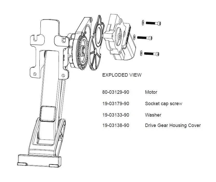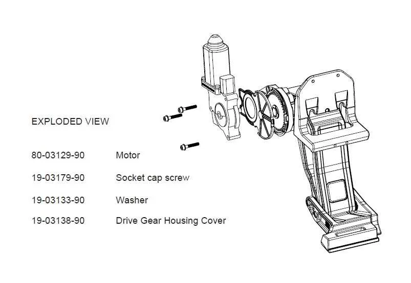
Ensure you have the necessary tools and materials before starting the installation. You will need a multimeter, wire stripper, and crimping tools. A reliable vehicle power source and clear space to work are also crucial for a smooth process.
Start by connecting the primary control module to the vehicle’s electrical system, typically using the battery’s positive terminal. Be sure to check voltage levels to confirm proper function.
The sensor connections are essential for activating the steps correctly when the door is opened or closed. These should be positioned near the vehicle’s door frame to detect movement efficiently. Use a sturdy, insulated wire to ensure safety and long-lasting performance.
After securing the main connections, verify each component. The motors should respond to signals, and the steps should extend or retract with ease. If any issue arises, check for any short circuits or loose connections, especially around the sensor points.
Lastly, test the entire system multiple times to ensure everything works smoothly and safely before finalizing the installation. Keep the vehicle’s electrical components protected from accidental damage during the setup process.
Installation Guide for Automatic Running Board Connection

Follow these steps to properly wire your automatic side steps to the vehicle’s electrical system:
- Identify the control unit location, typically near the vehicle’s door sill or under the vehicle frame.
- Locate the main power source, ensuring it is fused correctly. Use a dedicated fuse to prevent circuit overload.
- Connect the positive wire to the power source. This will allow the system to activate when the door is opened.
- Ensure the ground wire is properly connected to the vehicle chassis. This completes the electrical loop.
- Find the door switch or sensor. This component triggers the movement of the boards when the door is opened or closed.
- Wire the switch to the control module, ensuring the correct polarity is maintained for proper functionality.
- After the connections are made, secure all wiring with zip ties to prevent any interference with moving parts or the vehicle’s components.
Test the system by opening and closing the vehicle’s door, confirming that the steps deploy and retract as expected.
Understanding the Basic Connections for Powered Running Boards

To ensure proper functionality of your motorized steps, it’s crucial to follow these basic connection guidelines:
1. Ground Wire: The ground wire is essential for completing the electrical circuit. Always connect it to a clean, unpainted metal surface on the vehicle’s frame to avoid poor grounding, which can lead to malfunctioning components.
2. Control Module: The control unit is responsible for activating and deactivating the steps. This module requires a 12V power source, typically linked directly to the vehicle’s battery or fuse box. Ensure the fuse rating matches the system’s specifications to avoid damage during operation.
3. Motor Connections: The motors that power the steps require a dedicated 12V power feed, which should be run directly from the control module. Check the polarity of the wires, ensuring that the positive and negative are correctly matched with the motor terminals to avoid reverse operation.
4. Switch Integration: Some models use an external switch to manually control the extension and retraction of the steps. If applicable, connect the switch to the wiring harness leading to the control unit. Ensure proper placement for easy access, typically near the doorframe.
5. Safety Sensor: Most systems are equipped with a safety sensor that detects obstacles. Wire this sensor according to the manufacturer’s instructions, ensuring it’s properly integrated with the control module for automatic retraction when an obstruction is detected.
6. Power Supply Protection: For extra safety, install an inline fuse or circuit breaker between the battery and control unit. This protects the system from overloads or short circuits, preventing costly damage to the electrical components.
Following these steps ensures that your system functions correctly, prolonging the life of the components and maintaining safe operation. Make sure to double-check each connection before powering up to avoid any misconfigurations that could lead to malfunction.
Step-by-Step Guide for Troubleshooting Power Step Wiring Issues
Check the connections between the motor and the power source. Loose or corroded connections can prevent the system from functioning properly. Ensure that all terminals are securely attached and free from rust.
Inspect the control module for any visible damage or malfunction. If the unit appears faulty, it might need to be reset or replaced. Refer to the system’s manual for specific reset instructions.
Test the fuses. A blown fuse is one of the most common reasons for malfunction. Locate the fuse box and replace any damaged fuses with the appropriate rated ones.
Verify the ground connection. A weak or broken ground connection can disrupt the system’s operation. Make sure that the ground wire is clean and tightly secured to a metal surface.
Examine the motor for any signs of wear or failure. Over time, the motor may experience internal issues that can prevent it from working correctly. If necessary, test the motor with a multimeter to check for electrical continuity.
Check for interference from other electrical components. If other devices are drawing excessive power or causing surges, they can affect the performance of your system. Disconnect any non-essential electrical devices to see if that resolves the issue.
If the issue persists, consult the user manual for troubleshooting tips or contact a professional technician for further assistance.
How to Install the Electric Step System Correctly
Begin installation by ensuring all parts are present and undamaged. Start with mounting the brackets securely to the vehicle’s frame. Use high-quality bolts and tighten them to the manufacturer’s torque specifications.
Next, connect the main electrical components. Attach the positive wire from the vehicle’s battery to the control module, ensuring a solid connection with no exposed wires. Use appropriate connectors to avoid corrosion.
Install the motor assembly, making sure it’s aligned with the mounting points on both sides of the vehicle. Double-check the positioning of the linkage to ensure smooth movement when the system is activated.
The control module should be mounted in a dry, protected area under the vehicle’s body. Keep the wiring clear of heat sources or moving parts that could cause wear over time.
After securing the components, run the power wires to the module and motor assembly. Be meticulous in routing the cables to avoid any sharp edges or friction points that could lead to damage during use.
Once all connections are made, verify the system by performing a test run. Activate the mechanism several times to ensure smooth extension and retraction. If any irregularities are noticed, inspect all electrical connections and the positioning of the assembly.
Lastly, use the included fuses to protect the electrical system. Proper installation will ensure longevity and reliability, minimizing the chance of future issues.