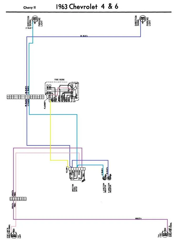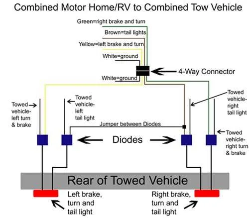
Ensure a secure connection between the signal switch and the rear indicator system. The process involves correctly identifying the wires responsible for triggering the rear signals when the pedal is engaged. Verify that the switch-to-rear connection is intact, as improper contacts can result in malfunction or delayed activation of the system.
Start by locating the wire that leads from the activation mechanism to the signal connectors. Use a multimeter to test continuity and voltage before proceeding with the setup. Once identified, connect it to the appropriate terminal on the rear unit, ensuring a tight, corrosion-free connection. Always use high-quality connectors designed for automotive applications to avoid wear over time.
If you’re troubleshooting, check for any broken or exposed wires. Insulate any damaged sections to prevent short circuits and ensure a stable flow of current. Also, inspect the grounding of the unit, as poor grounding can often lead to intermittent signal issues.
Important Tip: When performing a system check, ensure that all components are powered off to avoid accidental electrical damage. Make sure to follow the vehicle’s manual for any specific details on voltage and amperage requirements.
For improved safety, consider upgrading to a modern, relay-based switch. These systems offer better reliability and can handle higher currents without overheating or causing damage to sensitive components.
Proper Connection for Tail Signal System

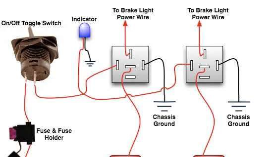
For reliable function, connect the red indicator wire to the power supply of the vehicle’s electrical system. Ensure the grounding is secure by attaching it to the vehicle’s chassis. The activating switch should be installed between the power source and the main circuit, ensuring it engages properly when the pedal is pressed. Use high-quality connectors to prevent corrosion over time and check the resistance regularly to maintain efficiency.
Run the signal conductor through the vehicle’s wiring harness, securing it along the path to avoid damage from moving parts. Ensure that the current flow does not exceed the designated amperage for the circuit. For multiple units, connect the subsequent units in parallel, ensuring all connections are tight and insulated to avoid short circuits. Test the system after installation to verify proper functionality.
Make sure to check for any potential shorts or ground faults before finalizing the setup. Apply dielectric grease to all connections to enhance longevity and performance. During installation, double-check that the power supply and grounding connections are not mixed up, as this could lead to malfunctioning of the entire system.
How to Identify Wires in a Signal System

Start by understanding the color codes for each wire in the circuit. This is crucial for correctly identifying their function. Typically, a red or green wire is used for power input, while a black one indicates ground or negative connection.
Follow these specific steps:
- Locate the power supply wire (usually red or green). It will be the one leading from the vehicle’s fuse box or battery.
- The wire leading to the system’s actuator is often yellow or blue. This is responsible for activating the device when the signal is triggered.
- The grounding wire, typically black or brown, is connected to the vehicle’s frame or a dedicated ground point.
- If there are multiple wires of similar colors, check for wire labels or use a multimeter to ensure accuracy in identifying the function of each wire.
Make sure to test connections before finalizing any modifications to ensure the components work properly and safely.
Steps to Connect Switch to the Harness
Start by locating the switch terminals. Identify the power input and output terminals on the component, typically marked as “IN” and “OUT.” Ensure the power supply is off before proceeding.
Next, prepare the connectors. Strip approximately 1 inch of insulation from the wire ends that will connect to the switch. Use a wire stripper for a clean and precise removal of insulation.
Connect the first wire from the power source to the “IN” terminal. Secure it with a crimp connector or terminal ring, ensuring it is tightly attached for a reliable connection.
Then, connect the second wire from the “OUT” terminal to the vehicle’s main control circuit. Use a similar crimp method to ensure the wire is firmly in place.
For safety, wrap the connections with electrical tape to avoid any short circuits or exposure to moisture.
Test the circuit by activating the control mechanism and checking for proper function. If any issues arise, recheck the wire connections for loose or improper contacts.
Finally, once functionality is confirmed, secure the wires with zip ties to prevent movement and ensure long-term durability.
Troubleshooting Common Signal System Issues
When the indicators aren’t functioning, start by checking the fuse. A blown fuse is often the culprit and can easily be replaced. Make sure to use a fuse with the correct amperage rating to prevent further damage.
Next, inspect the connectors for corrosion or dirt. Poor connections can disrupt the current flow, leading to non-functioning bulbs. Clean the contacts and ensure they’re firmly attached. If corrosion is severe, replacing the connectors might be necessary.
If the bulbs appear intact but don’t activate, check for continuity along the circuit. Use a multimeter to test for any interruptions in the flow, especially at key points like switches and connectors. A faulty switch might also cause an intermittent issue.
Worn-out or frayed cables are another common issue. Look for any visible damage along the wiring, particularly where the wires bend or enter the vehicle body. Cut and strip any damaged sections, then reattach them properly with high-quality connectors.
Ensure that the ground connection is solid. A weak or missing ground can cause inconsistent behavior or a complete failure of the system. Clean the ground terminal and ensure it has a direct, metal-to-metal contact with the chassis.
If none of the above steps resolves the issue, test the voltage at various points in the circuit. A voltage drop could indicate a problem with the power supply or an internal short. If necessary, trace the circuit from the power source to the bulbs to identify where the voltage loss occurs.