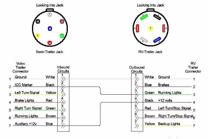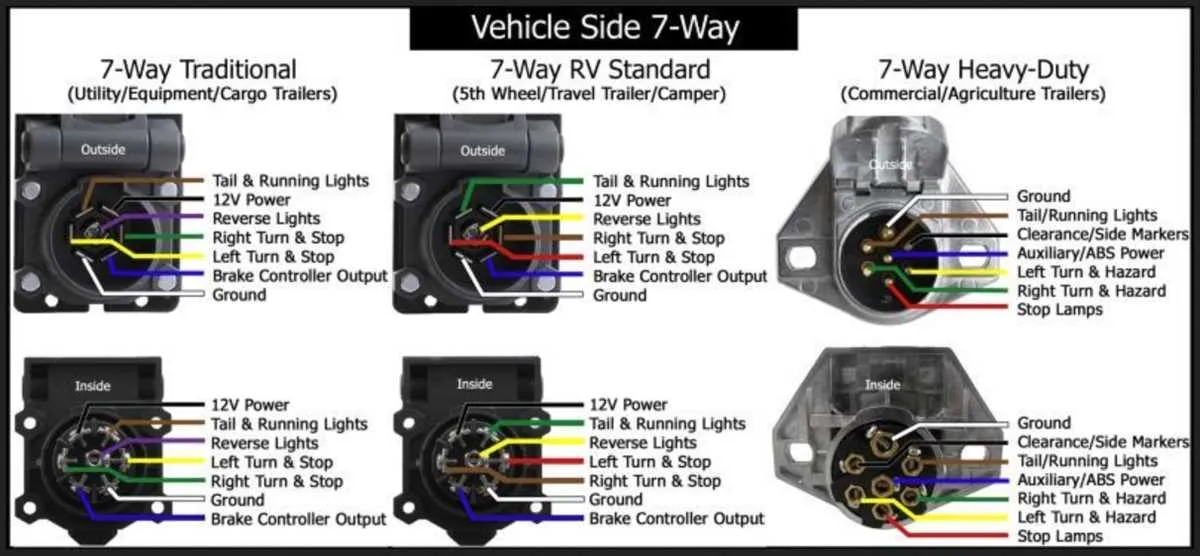
Always match the connector’s configuration to the tow vehicle and the hauled unit to prevent malfunctions. The standard seven-slot format used in North America follows a specific arrangement: each contact corresponds to a distinct function such as stop signal, tail illumination, ground, left and right blinkers, reverse gear trigger, and auxiliary power.
Center contact typically delivers backup lamp activation, while position three on the left side (facing the socket) is grounded. The lower right section generally controls brake engagement or electric actuation, depending on the model and usage type.
Use a multimeter to verify each terminal’s output before making permanent connections. Pin number one (top left) usually manages the left turn indicator, while pin number four (top right) is commonly designated for the right turn. Ensure that pin five supplies constant 12V power only when required, especially with delicate onboard electronics.
For enhanced safety, apply dielectric grease to prevent corrosion, and confirm secure mechanical locking to avoid unexpected disconnections during transit. Label each line based on function for future diagnostics and avoid color coding assumptions, as these may differ by manufacturer or region.
7-Pin Connector Layout and Functions
Start by locating the flat edge on the round socket to ensure correct orientation. At the top center position (12 o’clock), assign the yellow conductor for the left indicator. Moving clockwise, the next point (1–2 o’clock) should carry the green line for the right indicator.
At the 3 o’clock position, use the brown path to control rear marker lamps. Continuing to 5 o’clock, place the blue channel for electric brake engagement. At 6 o’clock, designate the white lead as the grounding path for the entire system.
The 7 o’clock terminal supports auxiliary charging via the black route, essential for battery recharge or interior illumination. Finally, the 9 o’clock pin is reserved for the red pathway to manage brake lights. Confirm each line with a multimeter before activation.
Color-coded functions for each pin in a 7-wire trailer connector

Always connect the brown conductor to the tail and marker lighting system. This ensures visibility during low-light conditions.
Use the yellow line exclusively for the left turn signal and hazard indication. It must be linked to the vehicle’s corresponding circuit.
Green is designated for the right turn and hazard flashers. Confirm synchronization with the towing vehicle’s output to avoid signal delays.
The white lead functions as the main ground path. Secure it directly to a clean metal surface on both ends for stable operation.
Blue is intended for electric brake activation. It must be routed through a brake controller and fused properly to maintain control.
Red or black typically serves the auxiliary or reverse lighting circuit. Identify its purpose before installation to prevent circuit conflicts.
Orange or purple delivers 12V auxiliary power. Ensure it’s protected with an inline fuse close to the source to avoid overloads.
Step-by-step guide to wiring a 7-pin trailer plug from scratch
- Mount the connector housing securely at the rear of the vehicle, ensuring full access to the terminals.
- Strip approximately 7–10 mm of insulation from each conductor to ensure solid contact with terminals.
- Use a multimeter to verify which line corresponds to each vehicle function: brake illumination, tail lighting, left and right turn indicators, reverse light, electric brakes, and ground.
- Insert each lead into the corresponding terminal:
- Pin 1 (Left signal) – Yellow conductor
- Pin 2 (Reverse gear circuit) – Black lead
- Pin 3 (Earth return) – White strand
- Pin 4 (Right indicator) – Green line
- Pin 5 (Parking lights) – Brown filament
- Pin 6 (Brake circuit) – Red output
- Pin 7 (Auxiliary or brake controller) – Blue core
- Tighten each terminal screw firmly to avoid intermittent contact, and check for any stray filaments that could cause a short circuit.
- Secure the cable bundle with grommets and clamps to prevent chafing or movement during operation.
- Test each function with an assistant activating the vehicle controls to ensure correct setup before road use.
Common troubleshooting issues with 7-wire trailer connections
Start by checking the ground path between the towing vehicle and the load carrier; corrosion at the grounding point is the most frequent cause of lighting failures. Ensure the contact surface is clean, rust-free, and securely fastened to bare metal.
If turn indicators or brake lamps malfunction, inspect the corresponding metal terminals inside the socket and coupler for oxidation or physical deformation. Bent pins often cause intermittent connection under vibration. Use a multimeter to verify continuity and signal presence.
Inconsistent power to auxiliary functions like reverse lights or battery charging often points to a blown fuse or poor voltage at the source. Trace the feed line back to the towing unit’s junction box, confirming proper amperage with a voltmeter under load.
Moisture ingress can lead to short circuits. Examine the rubber grommets and weather seals. Replace cracked or brittle coverings, and apply dielectric grease to contact points to prevent future oxidation.
For ABS signal loss or electric brake issues, check for wire gauge mismatch or damage near moving parts. Use shielded cabling where electromagnetic interference is present, and verify that controller calibration matches the number of axles in use.