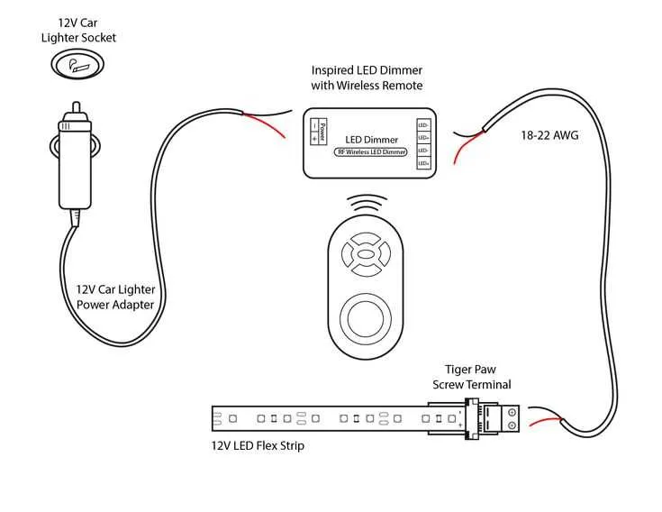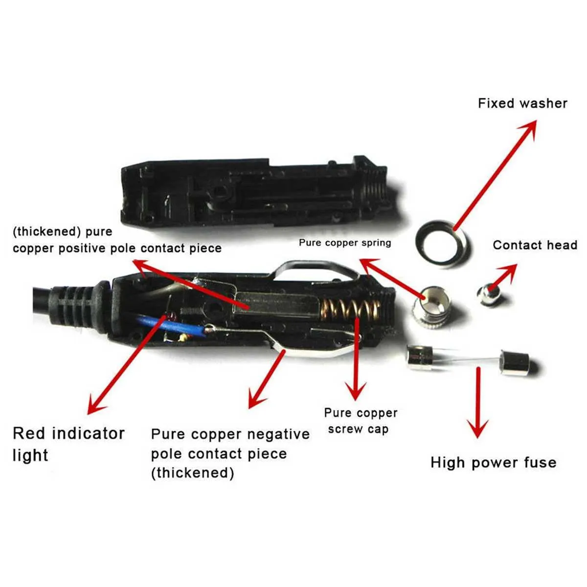
If you’re looking to install or troubleshoot your vehicle’s accessory power socket, it’s essential to follow the correct steps for connecting the electrical components. The socket typically requires a direct power connection from the vehicle’s battery or fuse box, with attention to voltage and amperage ratings to ensure proper functionality and safety.
Start by identifying the correct wires–usually, the positive lead is red, and the negative lead is black. Ensure that the positive wire is connected securely to the power source, while the negative wire should be grounded to a metal part of the vehicle’s frame. Failure to do so can lead to malfunction or potential hazards.
Use a reliable fuse to protect the circuit. This fuse should be rated according to the maximum current your socket can handle, typically around 15 amps. Always check the vehicle’s manual for the recommended fuse rating before proceeding with any installation or repairs.
Testing the system is crucial once all connections are made. Ensure the socket powers up when the ignition is turned on, and verify that all accessories work as intended. Regular checks can prevent future electrical issues and prolong the life of your vehicle’s systems.
Power Socket Installation and Connection
Ensure the power source is fused to prevent electrical overload. The positive terminal should connect to the main supply, while the negative terminal must be securely grounded to avoid short circuits. For consistent voltage, use a heavy-duty wire capable of handling the required amperage.
Route the wiring through a secure channel, avoiding areas with excessive heat or friction. Use quality connectors to establish reliable connections that resist corrosion over time. Insulate all exposed wire sections to minimize the risk of accidental shorts or electrical hazards.
Install a suitable switch that controls the power flow, ensuring that the connection remains intact only when necessary. This minimizes battery drain and prolongs the system’s lifespan. Always verify the polarity before connecting the unit to avoid damage or malfunction.
Understanding the Power Supply for Vehicle Charging Ports
Ensure proper power management for your vehicle’s charging port to prevent damage to the electrical system. Here’s how to optimize the power supply:
- Use a dedicated fuse: A 10-20 amp fuse is commonly used to protect the circuit from overcurrent situations. Choose the right fuse based on the amperage requirement of the device being powered.
- Choose suitable wire gauge: The wire should be thick enough to handle the required current. For most systems, a 12 AWG wire is adequate for distances under 5 feet.
- Connect to the battery directly: The most reliable connection is through the vehicle’s battery, using a direct connection to ensure stable power flow.
- Grounding: Proper grounding is crucial to avoid power loss or potential electrical hazards. Ensure the ground connection is clean and secure.
- Use a voltage regulator: For consistent performance, a voltage regulator can help maintain a stable voltage, especially if the vehicle experiences voltage fluctuations.
For installations requiring additional power, ensure that the system is able to handle the total load without overloading any part of the circuit. Regularly check connections for wear and tear to avoid power failures.
Wiring Connections for Installing a Car Lighter Socket

Connect the positive terminal of the accessory socket directly to the fuse box using a 12 or 14 AWG copper conductor. Choose a circuit that is ignition-switched to prevent battery drain when the engine is off.
Insert an inline fuse rated between 10A and 20A within 6 inches of the power source. This prevents short circuits and protects the harness from overheating.
Secure the ground lead to a bare metal point on the chassis. Use a ring terminal and self-tapping screw, ensuring solid contact with no paint or corrosion.
Do not share the ground point with high-draw components like amplifiers or starters. Use a separate grounding location to avoid voltage drop or signal interference.
Test the socket using a multimeter. Confirm 12V DC at the center contact and continuity between the outer shell and chassis earth before connecting any load.
Safety Tips for Wiring and Installation
Disconnect the negative terminal of the battery before any electrical work to prevent shorts and accidental arcing.
Use a dedicated fuse rated between 10A and 20A, installed no more than 6 inches from the power source, to protect the circuit from overload.
Ensure all connectors are crimped firmly using a ratcheting crimper, not twisted or taped, to guarantee long-term reliability under vibration.
Route all conductors away from heat sources such as the exhaust manifold and avoid sharp edges that may wear through insulation.
Select stranded copper wire with a cross-sectional area of at least 16 AWG; for longer runs, use 14 AWG or thicker to minimize voltage drop.
Secure all lines with insulated clamps every 18 inches to prevent chafing and movement.
Test continuity with a multimeter before reconnecting power, verifying both ground integrity and correct polarity.
When connecting to the dashboard panel, use OEM-style terminals and avoid splicing into factory harnesses unless absolutely necessary.