Start by checking the connection from the intake manifold to the brake booster. This hose should be thick, reinforced, and free from cracks. A weak seal here will cause poor brake performance and idle instability.
Next, locate the control tubing going to the HVAC system actuator. It typically branches from the intake plenum and routes through a check valve. If your climate controls are stuck or default to defrost only, inspect this segment first.
The emissions purge circuit relies on a smaller conduit linking the charcoal canister to the intake. Make sure the solenoid-controlled path is intact and not kinked. A malfunction in this area may trigger engine codes related to the EVAP system.
Inspect the EGR valve control feed. It generally runs from a solenoid mounted near the firewall. If disconnected or leaking, expect rough acceleration or failed emissions tests.
Finally, trace the source tubing for the cruise control servo. It commonly splits off near the throttle body and runs to a diaphragm unit. If cruise is non-functional, ensure this passage holds pressure under vacuum conditions.
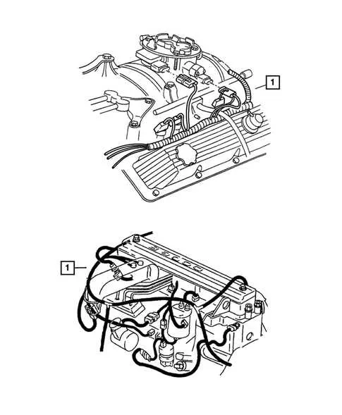
2001 Dodge Ram 1500 Vacuum Line Diagram
Begin by checking the hose routed from the intake manifold to the purge solenoid. Cracks or brittleness in this section often lead to rough idle and poor fuel economy.
- Trace the conduit leading from the throttle body to the cruise control actuator. Ensure a tight seal at both ends, as leaks here disable the system.
- Inspect the channel running to the HVAC control unit inside the cabin. If airflow doesn’t switch between vents properly, this path is the primary suspect.
- The emission control routing includes a line to the EVAP canister located near the fuel tank. Any disconnection triggers error code P0440 or P0455.
- Verify the connection to the brake booster check valve. A hissing sound during engine operation often indicates a failure in this region.
Use a handheld vacuum tester to confirm consistent pressure across all connections. Replace any tubing with reinforced silicone alternatives to prevent future degradation.
Vacuum Routing for Emissions Control Components on 5.9 Magnum Engine

Connect the intake manifold port directly to the purge solenoid inlet using a reinforced rubber conduit. From the purge solenoid outlet, route flexible tubing to the vapor canister, ensuring no kinks or cracks that might affect pressure consistency.
The EGR valve requires a separate manifold source. Use a dedicated molded hose from the throttle body area to the thermal vacuum switch mounted on the intake manifold. From there, another conduit leads to the EGR diaphragm. Confirm that the thermal switch closes when coolant temperature is below operating range to prevent early actuation.
For the MAP sensor, attach a short, direct hose from the rear manifold tap. Avoid teeing this connection with any emission-related system to prevent false readings. Secure all joints with OEM-style clamps to prevent leaks.
The cruise control servo uses a separate source; do not share it with any emission circuit. Use a one-way check valve inline to preserve reservoir pressure under load changes.
Ensure the HVAC controller receives its own tap from the plenum chamber, routed through a small plastic tube with a check valve to maintain door position during wide-open throttle conditions.
Inspect all pathways for routing away from exhaust surfaces. Use factory clips and retainers to secure routing along the firewall and under the intake area. Replace any brittle connectors with updated nylon fittings for durability.
Correct Vacuum Line Connections to Intake Manifold and Brake Booster

Connect the booster hose directly to the upper rear port on the plenum chamber. This fitting is usually located behind the throttle body and provides constant engine suction.
Do not use any tee fittings between the manifold source and the booster; this may cause insufficient brake assist due to shared flow.
Inspect the one-way valve integrated into the hose leading to the servo unit. The arrow on the valve must point toward the brake assist diaphragm to prevent reverse airflow.
If equipped with a cruise control module, route its hose to a separate port on the throttle body or intake runner–not shared with the booster connection.
Ensure all junctions are sealed with clamps or factory-style connectors to avoid pressure leaks. Cracked or soft rubber sections should be replaced with reinforced tubing rated for engine compartment temperatures.
Use the port on the passenger side of the intake runner only for emission controls or HVAC actuation, not for brake support.
Common Leak Sources and Hose Replacement Guidelines

Check the intake manifold gasket area first–any crack or wear around the junction can disrupt engine performance. Use carburetor cleaner spray while the engine runs to pinpoint irregular idle caused by air seepage.
Inspect the rubber connectors near the throttle body and EGR solenoid; hardened or cracked elbows frequently cause pressure loss. Replace with high-temperature silicone tubing rated for engine bay conditions.
Trace emissions control paths, especially near the purge valve and charcoal canister. These components often use plastic connectors that degrade over time. Use reinforced hose and worm gear clamps during reinstallation.
Examine the cruise control actuator and HVAC reservoir routing. These systems rely on consistent suction; any brittle tubing or loose junctions can cause system failure. Replace all soft lines over 10 years old regardless of visible damage.
When replacing deteriorated tubing, match the inner diameter precisely and cut sections to the original length to avoid tension or slack. Avoid routing near high-heat surfaces; use protective sleeves if rerouting is necessary.