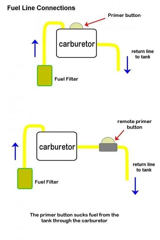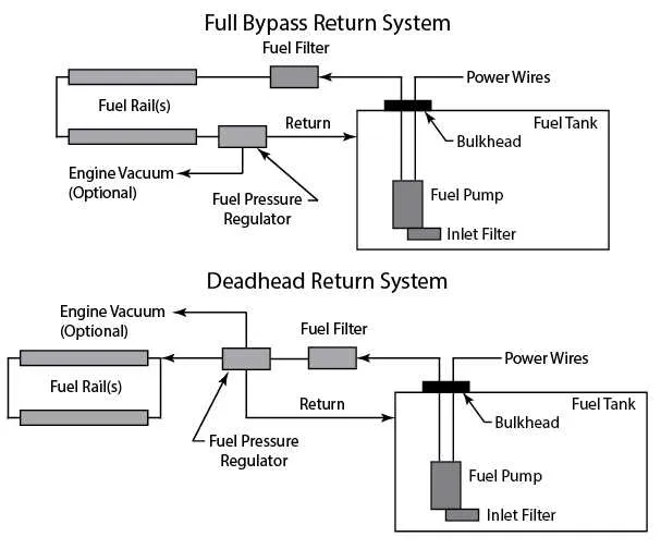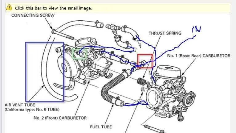
The correct routing of the liquid supply from the tank to the combustion chamber is essential for optimal engine performance. A detailed visual representation of how this system is organized can save time and prevent costly mistakes during repairs or upgrades. Ensuring that the connections are accurately positioned and sealed is key to maintaining the efficiency of the engine.
Identify key components: Start by focusing on the connection points, where the hoses link to the intake system and pump. These areas are crucial for a smooth and consistent flow. Check for any signs of wear, corrosion, or leaks, as these can significantly disrupt engine operation.
Ensure correct routing: Proper placement of each component in relation to others guarantees that the fluid moves seamlessly without interference. Avoid sharp bends in the hoses, as they can lead to pressure loss or restriction. Also, consider the material of the components – flexible rubber tends to degrade faster than more durable synthetic alternatives.
Regular maintenance: Over time, even the best systems can accumulate debris or develop small cracks. Inspect the system periodically to ensure there are no blockages or damage that could impede the flow. If you notice reduced engine performance or rough running, a thorough inspection and potential reconfiguration may be necessary.
Upgrade for efficiency: Many modern systems use more advanced materials and designs to improve flow and durability. Consider replacing old parts with newer, higher-performance versions if you’re looking to improve reliability or performance.
Understanding the Fuel System Routing

Ensure all connections are tight to avoid leaks. The intake manifold should be correctly aligned with the inlet tube for optimal performance. Start by connecting the hose from the pump to the intake system, making sure the fittings are secure and the path is clear of debris. Use high-quality rubber or nylon tubing that can withstand pressure without cracking or degrading over time.
Check the flow direction indicated on the component labels before attaching any hoses. This step prevents backward flow that could damage the internal parts. The pressure regulator must be placed before the main chamber to maintain consistent operation. Keep the tubes as short as possible to reduce resistance, avoiding unnecessary bends that could impede the flow.
After installation, inspect the setup for any potential points of failure, such as weak seals or exposed connectors. Tighten all clamps and secure the system in place to prevent shifting during operation. Periodically check for any blockages that could restrict the system, ensuring that the flow remains uninterrupted.
In case of maintenance, always replace worn hoses with those rated for the correct pressure range. When working on the system, use appropriate tools to avoid damaging the fittings. Lastly, always refer to the manufacturer’s specifications to ensure the components are compatible with the specific engine setup.
Understanding the Components of a Carburetor Fuel Line System
To ensure optimal engine performance, it’s crucial to grasp the main parts involved in the delivery system. The primary components include the fuel pump, filter, valve, and the various connectors that direct the flow from the tank to the combustion chamber.
The fuel pump plays a vital role in maintaining consistent pressure, ensuring an adequate supply of liquid to the intake system. When selecting a pump, ensure it’s rated for your engine’s specific requirements–too much pressure can cause flooding, while too little can lead to misfiring.
Fuel filters are essential for trapping contaminants that could clog the injectors or damage engine components. It’s recommended to replace these at regular intervals, usually every 12,000 to 15,000 miles, depending on your engine’s condition and usage.
Check valves prevent backflow, ensuring that pressure is maintained within the system. These components are often overlooked but are vital for avoiding performance issues caused by air pockets or fuel drainage.
Connectors and hoses should be inspected regularly for cracks, wear, or leaks. Over time, rubber or plastic parts can degrade, leading to potential fuel loss or dangerous fumes entering the engine bay. Replace any damaged parts promptly to avoid costly repairs.
Always verify the entire system for leaks after maintenance. Use a pressure test to confirm that the entire assembly is functioning properly, ensuring smooth engine operation and efficiency.
How to Identify Flow Direction in Engine Fuel System Schematics

To determine the proper flow direction of the system in your schematic, follow these steps:
- Locate the inlet and outlet ports: Identify the ports where liquid enters and exits the component. Typically, the inlet is located near the base, and the outlet is positioned higher.
- Follow the arrows: Most diagrams include directional arrows indicating the path of liquid through the system. If arrows are not present, proceed with the following steps.
- Check for filters and regulators: Inlet pathways are often connected to filters or pressure regulators, which help determine the flow direction. These parts usually sit at the entry point.
- Observe the components connected to the system: Components such as pumps or injectors will direct the flow. A pump generally pushes liquid from the lower portion to the higher part of the system.
- Examine connections for clues: Follow the tubing or pipes that connect the system to other engine parts. The placement of hoses can help you identify the direction of flow, especially if connected to intake manifolds or other related parts.
If unsure, inspect the system in action, as liquid flow typically follows the path of least resistance, moving from low pressure to high pressure regions.
Common Fuel Supply Problems and Their Fixes
If you’re experiencing poor engine performance, start by checking for clogged or damaged hoses. Over time, these can degrade and restrict the flow of essential liquids to the intake. Replace any cracked or brittle tubing immediately to ensure an uninterrupted supply.
Leaks at connection points are another frequent issue. Inspect all joints and fittings for signs of wear or seepage. Tighten or replace the seals, and ensure all clamps are secure. Use high-quality, heat-resistant materials for added durability, especially in engines with high temperatures.
Another culprit is air pockets, which disrupt the steady flow. Bleed the system to remove any trapped air, allowing for a continuous, even distribution. This simple step can restore engine stability and eliminate irregular idling or stalling.
Fuel contamination can cause uneven engine operation, particularly if debris or rust enters the system. Regularly clean your tank and replace any filters to prevent foreign particles from interfering with performance.
Lastly, excessive pressure buildup can cause parts to strain or fail. Check for blockages or restrictions that could be impeding normal pressure release. If necessary, adjust the regulator or replace damaged components to maintain optimal function.