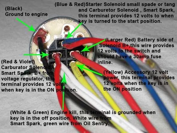
For a reliable electrical connection of your engine’s starter control, follow the provided schematic closely. Ensure that the main power feed is properly linked to the control terminal, and the ground wire is securely attached to avoid any operational faults.
Key points: Identify the terminals marked for battery input, accessory output, and the starter activation line. Use color-coded cables where possible to reduce installation errors. Always verify continuity before finalizing connections to prevent damage to the system.
Proper assembly of the control mechanism’s circuitry guarantees smooth operation of the ignition process. Avoid improvising with incompatible connectors or bypassing safety relays, as this can lead to failure or hazards.
Electrical Connection Guide for Kohler Start Control
To ensure proper functionality of the engine’s start mechanism, follow these steps for correct cable layout and terminal matching:
- Identify the main power input terminal, typically marked with a “B” or “Bat.” Connect the battery positive lead here.
- Locate the ground terminal, often labeled “G” or “Grd.” Attach the chassis or engine ground wire securely.
- Find the output lead to the starter solenoid, usually marked “S.” This line activates the starter relay when engaged.
- Connect the accessory terminal, if present, to power auxiliary components when the control is in the run position.
- Ensure all connectors are clean, free of corrosion, and firmly seated to prevent intermittent faults.
Follow these notes for troubleshooting or installation:
- Use a multimeter to verify continuity and correct voltage at each terminal.
- Match wire colors with the engine manufacturer’s specifications for accuracy.
- Replace any damaged connectors or frayed cables before assembly.
- Secure the control unit with proper mounting hardware to avoid vibration-related disconnections.
- Consult the engine model number to cross-reference terminal functions if labels are missing.
Identifying Wire Colors and Functions in Kohler Ignition Switch
Red wires typically carry constant battery power, supplying voltage directly from the main source.
Black wires often serve as ground connections, completing the circuit to ensure proper operation.
Yellow wires usually connect to the starter solenoid, activating the engine’s cranking mechanism.
Green wires commonly link to the alternator or charging system, managing electrical flow during operation.
Blue or white wires may correspond to auxiliary functions, such as lighting or safety interlocks.
Verify each conductor with a multimeter before connection to avoid miswiring. Trace wires from the main panel to confirm their role, as color standards can vary slightly between models.
Step-by-Step Connection Guide for Kohler Ignition Switch Wiring
Begin by identifying the main terminals: power input, starter output, and ground. Use a multimeter to confirm correct polarity before proceeding.
Connect the positive feed from the battery to the main terminal labeled “B” or “Bat.” Ensure a secure, corrosion-free connection.
Attach the starter lead to the terminal marked “S” or “Start.” This line activates the motor engagement when turned.
Link the ground wire to the chassis or designated grounding point, verifying continuity to avoid electrical faults.
For models with accessory terminals, connect devices like lights or auxiliary power sources to the “ACC” terminal, observing correct voltage ratings.
Use heat shrink tubing or insulated connectors on all joints to prevent shorts and moisture damage.
Double-check all connections for firmness, and test the control function by rotating the key or actuator through each position.
If the system fails to respond, inspect fuse integrity and verify circuit continuity using a tester.
Troubleshooting Common Electrical Connection Issues in Kohler Ignition Systems
Start by checking for loose terminals. Vibrations often cause connectors to loosen or disconnect, interrupting the current flow. Firmly press and tighten all plugs and fasteners to ensure secure contact.
Inspect the continuity of cables. Use a multimeter to test each lead for breaks or high resistance. Damaged insulation or internal wire fractures can cause intermittent failures or complete loss of power.
Look for corrosion buildup on contact points. Oxidation on metal surfaces increases resistance, leading to poor signal transmission. Clean terminals with a wire brush or electrical contact cleaner to restore conductivity.
Verify proper routing of the harness. Avoid sharp bends or pinched sections that can cut conductors. Reroute any cable bundles away from heat sources or moving parts that could cause damage over time.
Check the ground connection integrity. A weak or missing earth path leads to erratic operation. Tighten ground screws and confirm the metal surface is clean and free of paint or rust.
Test the operation of the actuator mechanism. Mechanical wear or internal faults can cause failure to engage the system. Lubricate moving parts and replace any defective components to ensure smooth function.
Following these steps will isolate and resolve most faults related to the control unit’s electrical path.