If you’re looking to replace or repair the rear illumination system on your motorcycle, it’s essential to understand the proper connections for each component. Accurate wiring ensures safety and functionality. Make sure to identify each lead’s role before starting any project to avoid common mistakes.
The ground connection typically uses a black wire, while the brake signal is often delivered via a red or orange lead. For turn signals, a yellow or green wire is commonly employed. These are general practices, though variations may exist depending on the manufacturer or model.
Before you start, always consult your specific motorcycle’s service manual. This will provide detailed color codes for your model, helping you avoid confusion and potential wiring issues. If the manual is unavailable, using a multimeter to test the continuity of each wire is another way to verify the function of each lead.
Wiring Connection for Motorcycle Rear Illumination
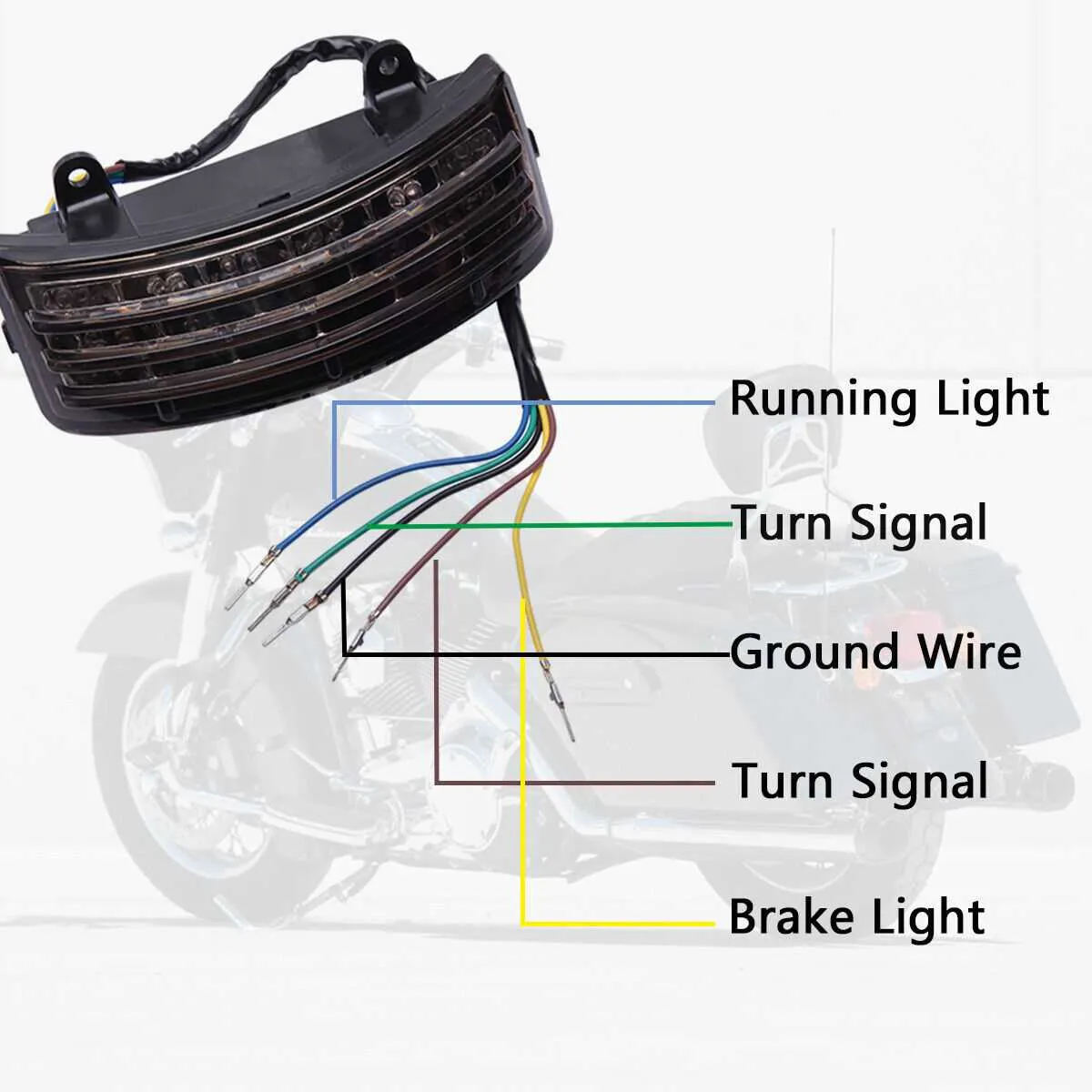
For proper installation, start by identifying the ground connection, which is typically a black wire. This should be securely attached to the metal frame of the vehicle. The brake signal usually uses a red or orange wire, while the running light typically uses a brown or yellow wire. Make sure to check the harness instructions to confirm color coding, as variations can exist based on the model and year. Always ensure connections are waterproof and properly insulated to avoid electrical issues.
If installing a custom setup, you may need to use a multimeter to verify connections before securing the wires in place. For a clean installation, it’s advisable to use heat shrink tubing or electrical tape to insulate and prevent any exposure to moisture or wear. When connecting to the power source, ensure the voltage matches the specifications for your system to avoid overheating.
For optimal performance, double-check each wire for continuity and make sure the connections are tightly secured. After completing the wiring, test the entire system by activating the brake and running light functions to ensure proper operation before finishing the installation process.
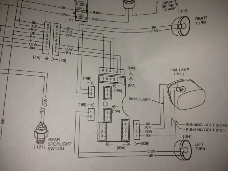
Understanding the Wiring Color Codes for Harley Davidson Tail Lights

For proper installation or troubleshooting, knowing the correct wiring scheme is key. The rear illumination system typically uses a few standard color codes to distinguish between functions. The most common color for the positive wire is usually red, while black is generally reserved for the ground connection. The brake circuit often utilizes a different color, like green, to separate it from the running illumination.
When working on the rear electrical setup, always double-check the connections before finalizing the installation. Incorrect wiring can cause malfunctioning lights or even a short circuit. It’s crucial to confirm that the brake and running light circuits are properly aligned to prevent interference between them.
To identify the functions more easily, use a multimeter to test each wire before making any permanent connections. Ensure the correct voltage is present across the system to avoid damaging the components.
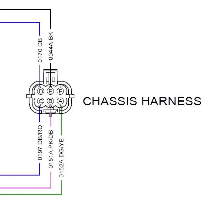
If you are replacing or modifying parts, make sure to follow the color code specifications for your specific model. Different models may slightly alter the wiring, so cross-reference with the technical manual for accurate details.
How to Identify and Replace a Faulty Harley Tail Light Wire

Start by inspecting the electrical connections of the rear illumination system. If the bulb is not lighting up, check the power supply for any breaks or loose connections. Verify that the voltage is consistent using a multimeter to identify any short or faulty circuit.
Next, disconnect the negative terminal of the battery to prevent any shocks or accidental power surges. Begin with the connectors that link the rear assembly to the bike’s electrical system. If the connections appear corroded or worn out, replace them with new, high-quality connectors to ensure a solid link.
If you find any visible signs of damage, such as frayed or exposed parts, it’s time to replace the damaged segment. Cut out the affected area and strip the insulation carefully to expose fresh wire. Use a proper crimping tool to attach new connectors, ensuring the joins are tight and insulated.
When reassembling, always check that the wires are secured properly and do not interfere with any moving parts or sharp edges. Test the system before fully reattaching the cover to confirm everything is functioning as expected.
For advanced issues, consider testing the ground connection as well, as poor grounding can cause intermittent malfunctions. Ensure that the ground wire has a strong contact with the frame, as any rust or paint between the wire and the frame can cause electrical issues.
Step-by-Step Guide to Wiring a Motorcycle Rear Electrical Components for Custom Installations

To successfully connect the rear electrical components of your bike for a custom setup, follow these steps:
- Identify the necessary connectors: Before beginning, ensure you have the right connectors that match the system you’ll be working with. You may need terminal connectors, bullet connectors, or other specialized types for secure fits.
- Prepare the installation area: Remove any covers or parts that may obstruct access to the rear area. Clean the contact points to avoid corrosion or connection issues later.
- Connect the grounding wire: Start by connecting the ground to the frame. This ensures proper electrical return for the system. Attach the ground wire securely to a clean, unpainted section of the metal frame to maintain a solid connection.
- Attach the brake signal cable: Next, identify the wire designated for braking signals. This is typically a thicker cable and should be connected to the brake switch on the bike’s front or rear mechanism, depending on your model.
- Hook up the running signal cable: The wire for the running signal will usually be thinner. Connect this to the appropriate terminal that runs directly to the power source for steady illumination.
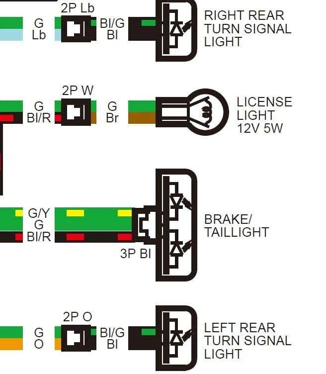
- Secure the turn signal wires: Turn signal cables must be linked to the left and right signal terminals respectively. Ensure each side is correctly wired to its corresponding indicator on the rear assembly.
- Test the system: Before sealing everything up, turn on the bike and test each function: brake, running, and signals. Ensure that all components light up as expected and that the signals function properly on both sides.
- Insulate and secure the connections: Once confirmed, use electrical tape or heat shrink tubing to protect all exposed sections. Secure the cables along the frame to prevent rubbing against moving parts or heat sources.
By following these steps, you can achieve a clean and functional installation for your motorcycle’s rear electrical components, ensuring both safety and aesthetic appeal.