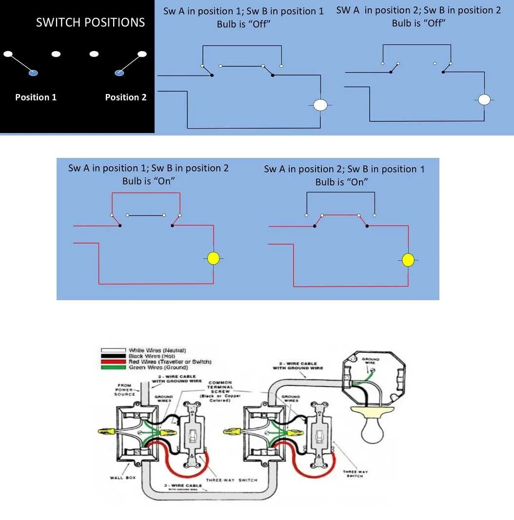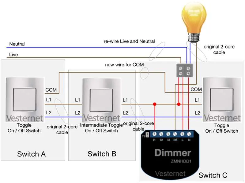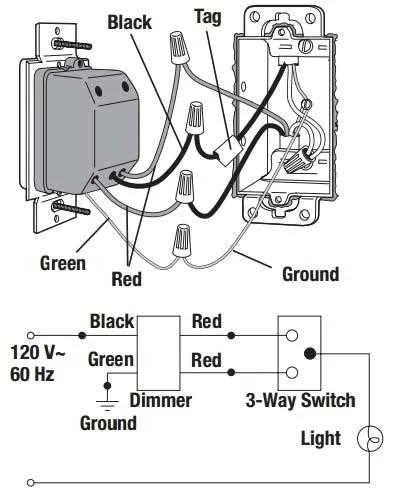
For a setup where two separate locations control the same light, you need to carefully connect multiple control points to the circuit. This configuration requires special attention to ensure the wiring is done correctly for safe and functional operation. It is essential to choose the right components and wire them in a manner that allows both controllers to operate independently.
Step 1: Begin by connecting the power source to the first control point. The common terminal of the controller will be linked to the live wire from the power supply. This ensures that the circuit has a continuous flow of electricity when activated.
Step 2: The second controller will be wired in parallel, with the traveler wires connecting both units. The key here is to ensure that the traveler wires are securely connected to both control units, allowing the flow of electricity to be routed properly depending on the position of each switch.
Step 3: At the light fixture, the load terminal must be connected to the light, which will be activated when the circuit is completed. This setup provides flexibility, allowing you to turn the light on or off from either control point.
Important tip: Double-check all connections and make sure the power is turned off before starting the installation. If done improperly, this wiring can cause short circuits or potential electrical hazards. If you’re unfamiliar with electrical work, it’s highly recommended to consult an electrician to avoid safety risks.
Wiring a 3-Pole Circuit Control

For controlling a light from two different locations, follow these steps to wire the circuit effectively:
- Ensure you have the correct equipment: two toggle units, a light fixture, and the necessary wires (typically black, white, and ground).
- Start by connecting the power source to the first unit. This unit will have two terminals for the hot (live) wire.
- From the first unit, run a wire to the second device, connecting the traveler terminals. These are typically marked as “common” and “traveler” on both ends.
- At the second location, connect the travelers to the respective terminals on the second unit. Attach the neutral wire to the light fixture.
- Finally, ground both units to ensure safety. Secure the ground wire to the grounding screw on each unit.
Check for continuity with a multimeter after the installation is complete to ensure proper operation. Properly labeled terminals simplify the process of identification and wiring each connection correctly.
Wiring Configuration for a 3-Way Switch System
To properly wire a system with two control points, use three-wire cables between the two devices. The common terminal of one unit connects to the power source, while the second device controls the load. For reliable operation, ensure the traveler wires are properly connected to the corresponding terminals on both units.
Key connection points: The power supply should be wired to the common terminal of the first unit. The traveler wires run between the two units and connect to the traveler terminals. Finally, the common terminal on the second unit is connected to the load (typically the light fixture).
Essential tips: Avoid crossing traveler wires, as this can cause malfunction. Also, ensure all connections are securely tightened to prevent loose contacts, which may result in intermittent operation.
Understanding Terminal Connections in a 3-Way Switch

The first terminal, commonly known as the “common” terminal, is where the power supply or the load (light fixture) connects. This terminal plays a crucial role in determining the flow of electricity depending on the state of the mechanism. It’s important to ensure that the wire leading from the power source or the fixture connects securely to this terminal.
The other two terminals, often referred to as “traveler” terminals, allow the device to change the flow direction between two separate lines. These terminals are used to connect two traveler wires, which are responsible for transmitting the signal to the second device in the setup. When wiring, ensure that these wires are installed correctly to guarantee proper functionality of the entire circuit.
A critical aspect of wiring involves recognizing the difference between the traveler terminals and the common terminal. Incorrectly swapping these can lead to malfunction, where the device fails to control the load as intended. Double-check the labels on the terminals before making any connections to prevent miswiring.
Proper connection ensures that each component in the system can alter the flow of electricity depending on the position of the mechanism, either turning the fixture on or off based on the terminal alignment. Always verify the correct matching of wires to their designated terminals for safety and efficiency.
Troubleshooting Common Issues in 3-Way Switch Circuits
Start by verifying that the wiring is correctly connected. Ensure that the traveler wires are properly attached to the correct terminals on both control devices. Miswiring is a common cause of malfunction, where the traveler wires are switched or not connected securely.
If the circuit doesn’t work at all, check for a faulty connection at the power source. Often, a loose or disconnected neutral wire can prevent the entire system from functioning. Ensure that the ground connections are intact, as improper grounding can lead to unexpected results.
If you experience inconsistent operation or flickering lights, it may be due to a loose connection at one of the switches or at the light fixture. Inspect all terminals for tightness, especially the screws holding the wires. Corroded or worn-out connections can also cause intermittent issues.
For cases where only one of the control devices is responsive, consider replacing the malfunctioning unit. Sometimes internal components, like the toggle or rocker mechanism, can wear out over time and fail to operate correctly, even though the wiring is intact.
If the light remains on or off regardless of the switch positions, inspect the wiring at both ends for any miswiring or crossed wires. A common mistake is connecting the wrong terminal on either device. Ensure the common terminal is connected to the correct wire leading to the power source or load.
Finally, test the circuit with a multimeter to ensure that voltage is present where expected. This can help identify any breaks in the circuit or faulty components that are preventing proper operation.