When setting up a motor controller, it’s crucial to follow the precise connection plan for reliable performance. A well-structured pinout layout ensures correct interfacing between the components and minimizes potential issues. Incorrect wiring can lead to system malfunctions or even damage to the equipment, so it’s vital to follow manufacturer recommendations for each terminal.
Ensure correct terminal identification to avoid errors. Label each connection point clearly to maintain consistency throughout the installation process. Pay attention to the voltage ratings and the required current capacities for each wire to guarantee safe operation. Additionally, verify that each wire is securely fastened to its corresponding terminal to prevent accidental disconnections during operation.
Use proper insulation materials to protect the wires and terminals. Insulation plays a critical role in preventing short circuits and electrical fires. It is recommended to use high-quality materials that meet the required standards for industrial environments. Always check the specifications of the cables and connectors before use to ensure compatibility with your system’s needs.
Perform a thorough system check after completing the electrical setup. This includes testing the entire setup before powering it up to confirm that all connections are secure and that the controller is functioning as expected. It’s also wise to double-check the grounding connections to avoid electrical hazards.
Electrical Connection Guide for the ETC619580 Model
Ensure all connections are made according to the provided technical documentation for optimal functionality. Verify that the input and output terminals are securely connected to the correct phases. For power input, connect the three-phase supply to the designated terminals, ensuring proper phase sequence and voltage matching. The ground terminal must be connected to a reliable earth ground to prevent electrical faults.
Control Wiring: For the control terminals, check that the control voltage is compatible with the unit’s requirements. Typically, a 24V DC control signal is used for start/stop commands. Ensure the correct polarity when connecting the control wires. For external devices such as sensors or switches, use shielded cables to avoid electrical noise interference.
Output Connections: Verify the connections for load terminals to match the rated current and voltage of the connected equipment. Ensure proper thermal management and protection through adequate fuses or circuit breakers rated according to the system’s power demands. The output terminals should be checked for secure and firm connections to avoid loose contacts that could lead to overheating.
Always double-check wire gauges to prevent overheating. Use wires with adequate cross-sectional area to handle the expected current without excessive voltage drop. For safe operation, it’s essential to maintain the manufacturer’s recommended installation practices, avoiding modifications to the system that could impact performance or safety.
Understanding Pinout Connections for Yaskawa ETC619580
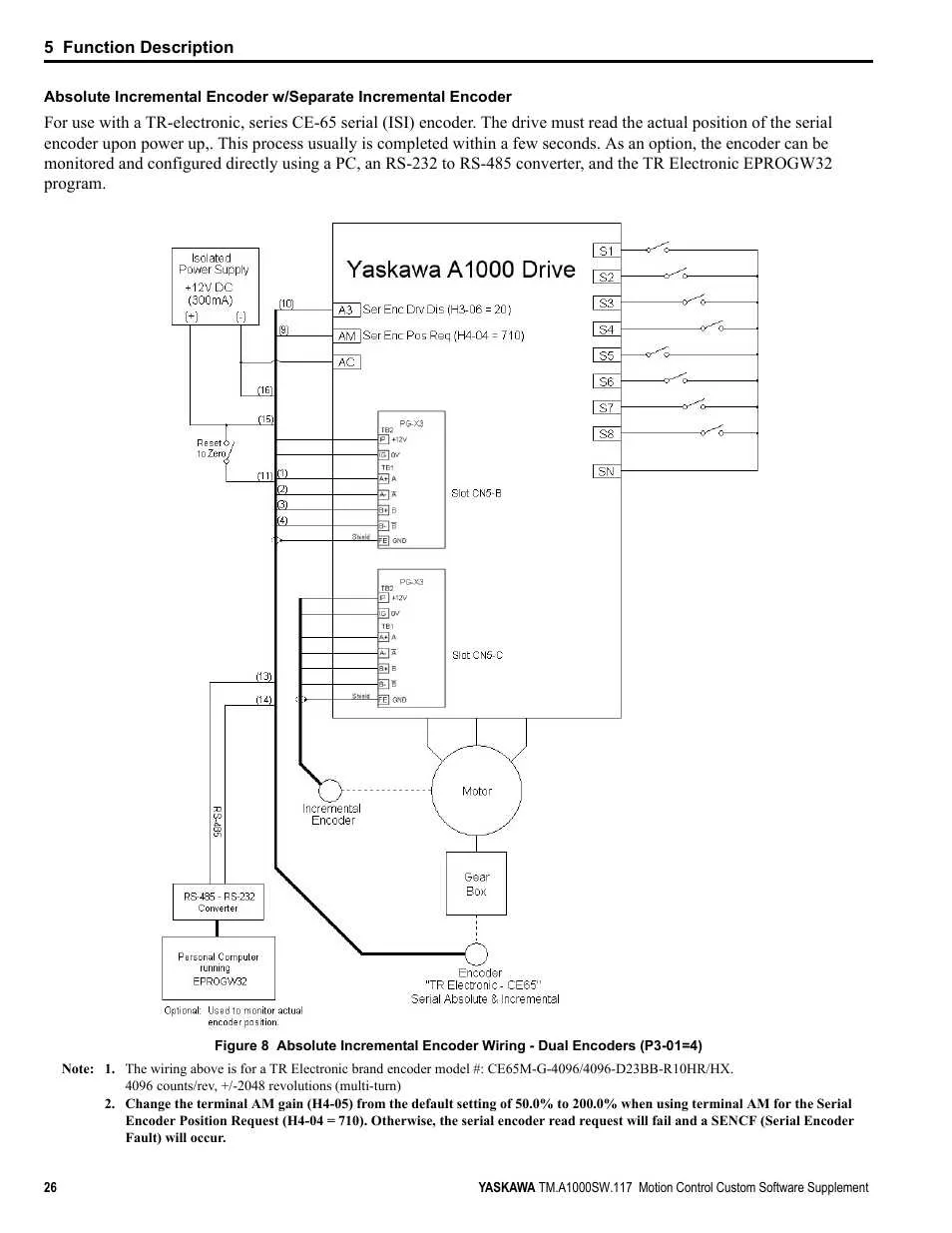
To correctly connect the terminals, follow the pinout specifications carefully. Ensure the right polarity for each wire to avoid short circuits or damage to components. Always use properly insulated cables to prevent accidental contact with adjacent pins.
Pay special attention to the control pins, which typically handle input/output signals for communication with external devices. These are often connected to signal controllers or monitoring equipment, so precise routing is critical for maintaining system integrity.
When wiring power input, ensure a stable connection to the designated ground pin to prevent electrical surges. This is crucial for ensuring that the equipment operates within its rated voltage range without causing harm to the internal circuitry.
If you’re working with data pins, check for proper termination and shielding to avoid interference. Data signals should be routed through twisted pairs or shielded cables to minimize noise, particularly in industrial environments where electromagnetic interference is common.
Double-check the physical layout of each terminal, as incorrect connections can lead to operational failures or malfunctioning of the system. It’s essential to ensure the correct matching of each wire to the appropriate terminal according to the configuration guide.
Step-by-Step Guide to Proper Installation for Optimal Performance

Ensure all power sources are disconnected before starting the installation process. This is critical for safety and preventing electrical shocks.
- Connect the main power input terminals to the appropriate power source, ensuring proper voltage levels are matched to the unit’s specifications.
- For ground connections, ensure the designated terminal is securely connected to the system’s ground to avoid electrical surges.
- Link the control circuit terminals to the input control system, verifying correct polarity for signals. Incorrect connections can lead to malfunction or damage to components.
- Connect the motor output terminals. The wiring must be routed properly to prevent overheating or loss of efficiency during operation.
- Verify each connection with a multimeter, ensuring continuity and proper voltage levels. Any discrepancies should be addressed immediately before powering up the system.
- Ensure all wiring is routed through designated channels to prevent short circuits or damage during operation. Keep wiring away from sources of heat or high interference.
Once all connections are verified, recheck the system’s setup for completeness. Ensure no loose wires are present, and confirm that all components are securely fastened.
- Power the system on in a controlled environment, observing initial behavior to confirm all components are functioning as expected.
- Perform a dry run to check for any irregularities in the operation. Listen for unusual sounds or monitor abnormal readings that might indicate incorrect installation.
- Make adjustments to parameters as needed based on initial testing results.
After confirming proper functionality, close any panels or enclosures to complete the setup. Regularly check the system’s performance to ensure continued safe operation.
Troubleshooting Common Electrical Connection Issues

If the system fails to power on, first verify the integrity of the power supply connections. Ensure that all terminals are securely fastened and there are no signs of damage or corrosion. A loose or oxidized connection can prevent the unit from receiving power properly. Inspect the input terminal for any potential short circuits, which may have occurred during installation or due to environmental factors.
In cases of erratic operation or failure to respond to commands, check the control signal connections. Verify that the control cable is securely attached and that there is no wear on the insulation. Intermittent connections can cause erratic behavior, so replace any damaged wiring and ensure proper grounding.
For issues with communication errors between modules, confirm that all communication lines are connected correctly and that there is no electrical noise interfering with the signal. Adding a ferrite core to the cable can reduce electromagnetic interference (EMI), improving the stability of the communication link.
If the system shows an overload warning or malfunctions under load, check the current sensor connections. An incorrect or loose connection can lead to faulty readings and improper functioning. Inspect the sensor wiring for any signs of wear or loosening and replace as necessary to restore accurate load monitoring.
Lastly, confirm that the system’s earth connection is intact. A missing or faulty ground connection can result in erratic system behavior or even complete failure. Ensure that the grounding conductor is properly connected to a suitable ground point, and that the connection is free from corrosion or loose contact.