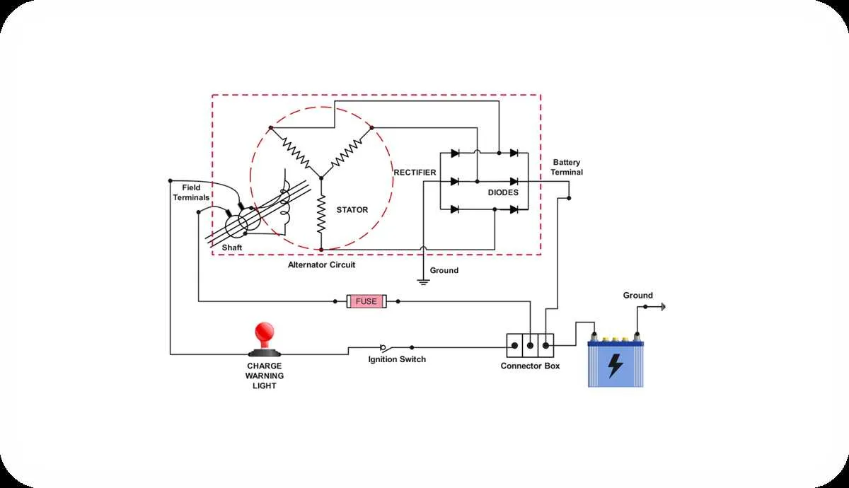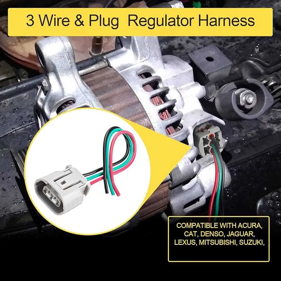
For proper electrical setup in vehicle charging systems, it’s crucial to grasp the essential connections between key components. Ensuring a stable flow of current involves connecting the regulator, stator, and battery effectively. The configuration typically includes a set of leads that manage both the excitation and grounding functions, ensuring the system remains efficient and functional.
When establishing the connections, always follow the correct sequence to avoid malfunctions or damage to sensitive electrical parts. The first lead should link directly to the regulator’s field terminal, often referred to as the F terminal. The second should facilitate the path to the stator, while the third completes the circuit by connecting to the battery’s charging input. These connections are vital for maintaining the overall performance of your electrical system.
To verify that all elements are functioning correctly, it is essential to check the voltage output after establishing the circuit. Ensure that the output voltage remains within the recommended range for the specific model of the vehicle. If you experience any inconsistencies or voltage drops, the issue may lie in one of these key connections, and further inspection is advised.
Tip: Always use high-quality connectors and ensure each lead is properly insulated. Poor-quality or worn-out components can lead to frequent electrical failures and reduced system longevity.
Wiring Setup for 3-Terminal Charging System
For an optimal connection, ensure the voltage regulator is securely attached to the stator, using the proper terminals for each lead. The first terminal connects to the battery, providing a stable charge to maintain voltage. The second lead should be attached to the ignition switch, allowing the system to activate when the engine is running. The third terminal is dedicated to ground, ensuring a safe and effective return path for the current.
Key points: Use high-quality connectors for each terminal to avoid any loose connections. Make sure the grounding terminal is properly secured to prevent electrical faults. Always double-check the connections to ensure no shorts are present before powering up.
Note: If you notice irregular charging or flickering lights, inspect the system for any loose or damaged leads. Regular maintenance and proper setup are crucial for reliable performance.
How to Identify the Three Main Wires in an Alternator Wiring System

The most important components in the electrical system of an engine are the connections for charging, ground, and regulator. To identify these, follow these steps:
1. The terminal that connects to the battery positive is typically the largest one, often marked with a “B” or “+” symbol. This is where the current flows to recharge the battery.
2. The ground terminal is generally the second most prominent connection. It is either connected directly to the chassis or to a grounded metal part of the engine. It is essential for completing the circuit and ensuring proper operation of the charging system.
3. The regulator lead is the smallest terminal. It controls the voltage output and is usually connected to the regulator or the voltage sensing system. This wire ensures the system does not exceed the preset voltage, which could damage other electrical components.
Verify each terminal using a multimeter to ensure correct voltage and continuity, confirming each connection’s function. Proper identification will prevent issues like overcharging, undercharging, or grounding failures.
Step-by-Step Guide to Wiring a Three Wire Alternator to Your Vehicle’s Electrical System
Begin by disconnecting the negative battery terminal to prevent shorts or sparks during installation.
Locate the output post on the charging unit, typically marked “BAT.” Connect this terminal directly to the positive post on the battery or to the starter solenoid’s battery side using an appropriate gauge cable–usually 10 AWG or thicker.
Identify the sensing terminal, often labeled “S.” Route a short lead from this post to the same point where the output connects–either the battery or the starter solenoid. This allows the voltage regulator to monitor system voltage accurately.
Find the exciter input, commonly marked “IG” or “L.” Use a switched 12V ignition source, such as a circuit active when the key is turned on. Insert a 1- to 2-watt 470-ohm resistor or indicator lamp inline to prevent backfeeding when the engine is off.
Ensure all connections are clean, secure, and properly crimped or soldered. Wrap terminals with heat-shrink tubing or electrical tape to avoid corrosion and shorts.
Reconnect the battery and start the engine. Measure voltage at the battery with a multimeter–it should read between 13.8V and 14.6V with the engine running, indicating proper charging function.
Troubleshooting Common Issues with 3-Leads Charging System

Begin by verifying voltage at the battery with a multimeter. With the engine running, expect 13.8–14.5 volts. If voltage remains at 12.6 or lower, proceed with the following checks:
- Inspect the primary output cable from the generator to the battery for continuity and corrosion at terminals. Resistance above 0.2 ohms indicates a fault.
- Test the exciter input (typically connected to the ignition switch) for 12V with key in “ON” position. Absence of voltage suggests an open circuit or faulty switch.
- Check the sensing connection (often linked to a fused junction or battery positive) for proper reference voltage. Use a test light or voltmeter to confirm presence of 12V.
- Confirm the charge indicator lamp functions. A burned-out bulb or open circuit can prevent field excitation.
- Examine ground continuity between the frame and the generator’s case. Use a jumper cable as a temporary ground to bypass potential grounding issues.
If output remains low despite good input signals, measure voltage directly at the output stud while the engine is running. If high at the stud but low at the battery, replace or clean the connecting cable.
For intermittent output, inspect internal regulator connections and look for worn brushes or damaged slip rings. A bench test can isolate internal defects.