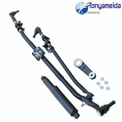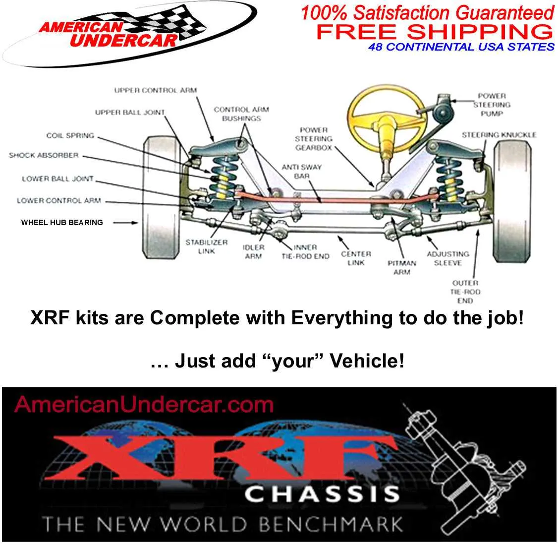
For accurate repair or modification of the wheel control system on a three-quarter-ton pickup, consult the detailed schematic specific to the model and year. This illustration clarifies component placement, hydraulic lines, and linkages, ensuring correct assembly and troubleshooting.
Focus on the power-assisted mechanisms and their connections to the main shaft and knuckles. Proper identification of the gear housing, tie rods, and drag links within the layout prevents misalignment and premature wear.
Use the wiring and mechanical layout to verify sensor locations and actuator connections, especially in units equipped with electronic aids. Referencing the exact blueprint reduces guesswork and supports efficient maintenance workflows.
Vehicle Control System Schematic
For proper maintenance or troubleshooting of the front axle directional control assembly, reference to the technical schematic is essential. Follow these instructions to ensure accurate interpretation and efficient repair:
- Locate the hydraulic power assist lines connecting the steering gearbox to the pump and reservoir.
- Identify the pitman arm position relative to the steering gearbox output shaft for alignment verification.
- Check the intermediate shaft coupling and universal joints for wear or binding.
- Trace the drag link connecting the pitman arm to the steering knuckle arm for any bends or damage.
- Confirm the tie rod ends’ integrity and correct adjustment for proper wheel alignment.
Key components on the schematic include:
- Hydraulic pump delivering pressure to the control valve
- Gearbox housing with input and output shafts
- Power steering fluid reservoir
- Control valve directing fluid to assist turning force
- Linkage arms transmitting movement to front wheels
Adhering to the schematic allows precise identification of hydraulic flow paths, mechanical linkages, and electronic sensor locations critical for system diagnostics and component replacement.
Identifying Key Components in the Heavy-Duty Truck’s Direction Control System
Start by locating the gearbox, which converts rotational input from the steering wheel into linear motion. It typically mounts on the frame rail near the firewall. Next, examine the pitman arm attached to the gearbox output shaft; it transfers motion to the linkage.
Inspect the center link (drag link), a horizontal bar connecting the pitman arm to the tie rods. Both inner and outer tie rods connect to the wheel spindles, allowing precise directional changes.
Check the idler arm on the opposite side of the pitman arm, which supports and stabilizes the center link, maintaining proper alignment during turns.
Verify the presence and condition of the steering shaft, including universal joints that connect the steering column to the gearbox, ensuring smooth rotational transfer without binding.
For vehicles equipped with power assist, identify the hydraulic or electric assist unit mounted near the gearbox or integrated into the system, noting fluid lines and electrical connections.
Confirm all ball joints and bushings within the linkage for wear or play, as these directly affect responsiveness and safety.
Use these component locations to cross-reference service manuals or technical schematics when diagnosing handling or control issues.
Step-by-Step Guide to Reading the Heavy-Duty Truck’s Wheel Control Schematic
Locate the power steering pump symbol first to identify the hydraulic source. Follow the lines from this point to trace fluid flow through valves and hoses. Note arrows indicating direction to understand pressure routes.
Identify the steering gearbox icon; it usually connects directly to the pitman arm component. Verify linkages between the gearbox and front wheel assemblies for mechanical movement translation.
Examine the sensor nodes along the control column for electrical signals related to feedback systems. These nodes often include torque sensors or angle detectors critical for electronic assist.
Check for annotations specifying wire gauge or hose diameter, which clarify capacity and pressure tolerances. This data helps in troubleshooting leaks or electrical faults.
Observe the layout of mounting brackets and fasteners indicated by dashed lines or specific symbols to ensure proper component alignment during maintenance.
Use the legend to decode abbreviations such as PS (power steering), ECU (electronic control unit), and others to match schematic elements with physical parts.
Verify the routing of control rods and hydraulic lines relative to the frame to prevent interference with suspension movement. Proper clearance ensures system reliability.
Cross-reference the schematic with the vehicle’s service manual for torque specifications and connector types associated with each component to avoid installation errors.
Troubleshooting Common Direction Control Problems Using the Schematic

Start by inspecting the linkage components for excessive play or visible wear. Focus on tie rods, drag links, and idler arms, as looseness here often causes wandering or delayed response.
Check the hydraulic assist lines and connections for leaks or cracks, which lead to reduced power assist and heavy turning effort. Replace damaged hoses or seals promptly to restore proper fluid pressure.
Examine the gearbox input shaft and pitman arm for damage or misalignment. Bent or worn parts disrupt the transfer of motion, causing uneven or jerky wheel movement.
Verify the condition of the ball joints by moving the wheels side to side while off the ground; any clunking or excessive movement indicates the need for replacement.
Review the fluid level and quality in the power unit reservoir. Low or contaminated fluid contributes to stiff or noisy operation. Flush and refill according to manufacturer specifications if contamination is detected.
Use the schematic to trace electrical connections related to electronic assist modules and sensors. Faulty wiring or sensor failures can produce intermittent assist loss or warning indicators.
Confirm proper adjustment of the center link and steering knuckles by measuring the toe-in angle. Incorrect alignment causes uneven tire wear and pulling to one side.
Inspect mounting brackets and bushings securing the entire directional control assembly. Worn mounts create vibration and loosen the feel of the wheel.