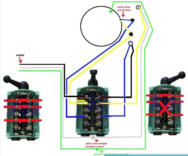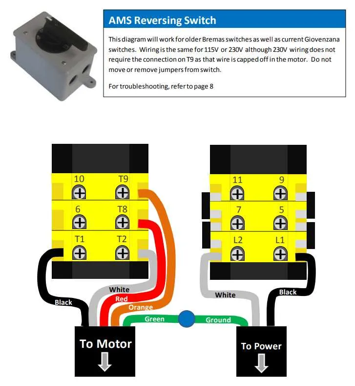
For a reliable multi-position selector setup, always verify the terminal numbering before attaching conductors. Use a continuity tester to confirm the internal contacts correspond with the intended connection points.
Ensure power is completely disconnected to avoid damage or injury. When joining cables, strip insulation precisely to avoid shorts, and secure all fasteners firmly to maintain consistent electrical contact under load.
Choose conductor thickness based on the current rating of the control unit; typically, 14 AWG is sufficient for circuits up to 15 amps. Label each lead clearly according to its function to simplify troubleshooting and future maintenance.
Consult manufacturer documentation for specific pin assignments and switching patterns, as configurations can vary significantly depending on the model and application. Employ color-coded wiring and protective sleeves for enhanced safety and clarity.
Control Unit Connection Guide
Connect the input power lines to the designated terminals marked L1, L2, and L3 on the rotary controller. Use appropriately rated cables to ensure safe current handling according to the motor’s specifications.
Output terminals should be linked to the motor leads matching the same phase sequence to maintain correct rotational direction. Confirm all contacts are tightened to prevent arcing or overheating.
When installing the selector device, ensure the neutral or common line is properly grounded or connected according to the motor control schematic to avoid electrical faults.
Use a multimeter to verify continuity between the control contacts in each position of the rotary mechanism, ensuring consistent switching without shorts or open circuits.
For reversing functions, confirm the crossover of phases on output terminals follows the recommended pattern, typically swapping two phases to reverse the motor rotation safely.
Insulate all exposed conductors with heat shrink tubing or electrical tape after termination to comply with safety standards and prevent accidental contact.
Selecting Correct Wire Gauge and Components for Drum Switch Installation

Use copper conductors with a minimum thickness of 14 AWG for circuits carrying up to 15 amps, and upgrade to 12 AWG when currents exceed this threshold to ensure safe current flow and minimize voltage drop. For loads surpassing 20 amps, opt for 10 AWG wires.
Insulation rated at least 600V is mandatory to withstand typical industrial and residential voltages without degradation. Choose heat-resistant types such as THHN or THWN for environments exposed to elevated temperatures.
Terminals and connectors must match the conductor size to avoid overheating and ensure solid mechanical connection. Use crimp or solder lugs compatible with wire gauge and secure them with appropriate torque settings specified by manufacturers.
Employ strain relief clamps or bushings where cables enter enclosures or panels to prevent abrasion and mechanical stress that may damage insulation over time.
For multi-position rotary devices, select insulated jumpers or pigtails with flexible stranded wire to maintain reliable contact and reduce mechanical fatigue during operation.
Always verify component ratings to correspond with the system’s voltage and current demands, avoiding under-rated parts that could compromise safety or performance.
Step-by-Step Connection Process for Single-Phase Rotary Control Setup
Start by turning off the main power supply to ensure safety during the entire installation. Identify the line (input) and load (output) terminals on the rotary actuator. Use a multimeter to verify no voltage is present before proceeding.
Connect the incoming live conductor to the common terminal of the rotary device, usually marked as “L” or “C”. Ensure the connection is secure and free of corrosion.
Attach the outgoing line from the load side to the output terminal marked as “T1” or “Load”. This will control the power flow to the motor or appliance.
Connect the neutral conductor directly to the load’s neutral terminal, bypassing the rotary mechanism. This ensures proper current return path and avoids circuit interruption.
Secure the grounding conductor to the metal chassis of the rotary control or to the grounding terminal, maintaining compliance with electrical codes and enhancing safety.
Verify all terminal screws are tightened to manufacturer-recommended torque values, typically between 1.2 to 1.5 Nm, to prevent loose contacts and overheating.
Use insulated tools and follow local regulations for protective measures. After completing connections, restore power and test the control by toggling it through its positions to confirm proper function and direction of rotation.
Troubleshooting Common Wiring Issues in Drum Switch Circuits
Always start by verifying continuity with a multimeter across each terminal point–open loops or unexpected resistance indicate a break or corrosion in contacts.
- Check for reversed line and load connections. Swapped leads can cause motors to hum, stall, or rotate in the wrong direction.
- Inspect mechanical interlocks and ensure contacts disengage fully when toggled. Partial contact can lead to arcing or overheating.
- Confirm that jumpers, if used, are placed according to motor type–particularly for reversing configurations involving single-phase versus three-phase systems.
- Measure voltage drop under load across each terminal. A drop of more than 5% may point to undersized conductors or failing components.
- Ensure neutral is not incorrectly used as a return path for current-carrying conductors–especially in installations with separate grounding schemes.
To isolate the malfunction, disconnect the actuator and test the control unit independently. Use a continuity checker to trace each path and confirm phase integrity. Replace any thermally damaged contacts immediately to prevent cascading failures.