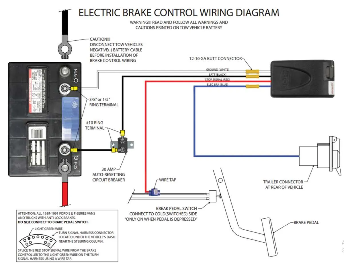
To ensure proper function of the braking system on a multi-axle vehicle, connect the power lines from the controller to each set of wheels in sequence. Start by linking the main power line to the first set of wheels, then run a secondary line to the second set, keeping wire lengths as short as possible. Use high-quality connectors and terminals to avoid corrosion and ensure a reliable connection over time.
Focus on wire gauge: It’s important to choose the correct gauge for each connection. For typical installations, a 10-gauge wire is recommended for the primary circuit, with 12-gauge used for additional connections. This ensures efficient current flow and prevents overheating.
Install a circuit breaker between the power supply and each wheel assembly. This will protect the system from overcurrent conditions and prevent damage in case of a fault. Be sure to test each wheel separately after installation to verify that the electrical signals are properly activating the brake components.
Final Check: Ensure that the wiring is secured in place with clips or ties to prevent wear and tear from road vibrations. Additionally, all connections should be thoroughly insulated to minimize the risk of short circuits, especially in wet conditions.
Effective Wiring for Two-Axle Vehicle with Electronic Braking System
To properly connect the braking system on a two-axle vehicle, follow this wiring guide to ensure safe operation and reliable performance. The key components to wire include the actuator, power supply, and control module, which all interact to apply the necessary force on the wheels.
- Power Supply: Connect a 12V DC power line to the brake controller for consistent power flow. The wire should be fused to prevent damage in case of overloads.
- Controller to Actuator Wiring: Use a dedicated, color-coded cable to link the electronic controller to the actuator on both axles. Make sure the positive and negative terminals are correctly aligned to avoid circuit failure.
- Grounding: A proper ground connection is essential for the system to function correctly. Attach the ground wire directly to the vehicle’s frame.
- Indicator Wiring: Connect an indicator light on the vehicle’s dashboard to monitor system functionality. This alert will help diagnose any faults in the system.
- Braking Force Adjustment: The wiring system must also allow for easy calibration of the braking force, with the controller offering manual and automatic modes for optimal stopping power under different load conditions.
Double-check all connections, especially where cables are exposed to wear, and ensure the wires are secured and insulated to avoid accidental short circuits or damage due to road conditions.
How to Identify and Connect Electrical Components for Trailer Brakes
To ensure proper operation of your vehicle’s stopping system, follow these steps to identify and connect the electrical components effectively. Begin by locating the connectors for the stopping system’s power feed, which should be clearly marked. These will typically be color-coded, with red indicating the primary feed. You’ll need to connect these leads to the main power source in your towing vehicle.
Next, ensure that the ground wire is properly attached to the chassis of the vehicle. This is crucial for completing the circuit and ensuring consistent operation of the system. A solid ground connection will prevent issues such as intermittent functionality or short circuits.
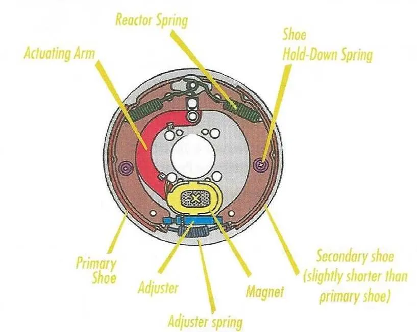
Each wheel’s actuator must be connected to the system. For each set, ensure the wire runs from the control unit directly to the brake drum or hub actuator. This is where the current will be delivered to engage the stopping components. Make sure each connection is secure and free from corrosion.
To prevent accidental disconnections, use quality connectors and ensure that all exposed metal parts are insulated. After completing the setup, test the system by engaging the vehicle’s brake controller to confirm that the stopping components activate correctly.
Finally, verify that all connections are tight, and there are no loose or frayed wires, as these can lead to malfunction or failure of the system. Regular maintenance checks will help identify any signs of wear and ensure everything continues to operate smoothly.
Understanding the Role of Brake Controllers in Tandem Load Haulers
Install a proportional controller for real-time pressure alignment with towing vehicle deceleration, ensuring even and reliable stopping force on all wheel pairs.
| Controller Type | Response Pattern | Best Use |
|---|---|---|
| Proportional | Instant, mirrors tow vehicle | Heavy loads, frequent operation |
| Time-Based | Fixed delay after pedal input | Lightweight hauls, occasional trips |
Calibrate gain using a 20 mph stop test, adjusting until hauler wheels resist firmly without locking. Excessive gain causes skidding; too little results in weak deceleration.
Provide a dedicated 12V power line and solid chassis ground to the controller, avoiding shared circuits that can introduce voltage drops and compromise performance.
Route signal leads directly from the controller to the rear connector, using sealed or heat-shrink terminals to protect against moisture and corrosion. Minimize splices to preserve signal integrity.
For electric-over-hydraulic systems, confirm compatibility or add necessary adapters to maintain precise pressure modulation across all wheel assemblies.
Common Wiring Issues and How to Troubleshoot Dual Axle Trailer Brakes

Begin by checking ground connections; a poor chassis ground often leads to weak or non-functioning stopping systems. Ensure the metal surface is clean, free of paint or rust, and the ground wire is firmly attached using a ring terminal.
Test the voltage at the connector using a multimeter. With the tow vehicle’s controller engaged, measure the output at the pin supplying power to the electromagnets. A reading below 12V typically indicates a fault upstream – often a damaged control unit, corroded plug, or frayed conductor.
Inspect splices and junction points. Moisture intrusion at these sites frequently causes corrosion, leading to resistance buildup or intermittent loss of current. Replace any corroded connectors and seal with heat-shrink tubing or dielectric grease to prevent recurrence.
Measure resistance at the hub magnets. Disconnect the feed wire and check across the magnet terminals; a typical reading ranges between 3–4 ohms per unit. Infinite resistance indicates an open circuit; near-zero suggests a short. Replace any defective components accordingly.
Trace the control wire along the frame. Look for pinched, cut, or abraded sections where insulation may have failed. Pay special attention near sharp edges or moving suspension parts where mechanical wear is common. Reinforce vulnerable areas with protective loom or reroute away from hazards.
Verify controller settings and calibration. Many proportional systems require adjustment to match the load weight; improper calibration can mimic electrical faults. Check the manufacturer’s manual for correct gain and boost settings, then test stopping response under controlled conditions.