To ensure the correct operation of the gear selector mechanism in your vehicle, it is crucial to understand the correct placement and configuration of the control components. First, check that the sensor is properly aligned with the transmission system to avoid malfunction. This element is essential for preventing unintended shifts and securing safe engine start-up only when the transmission is in the right position.
Accurate connection to the vehicle’s electrical system is vital for seamless communication between the gear lever and the engine control unit. Verify that all terminals are clean, tightly connected, and protected against moisture to prevent signal loss or short circuits. Utilize a multimeter to test each connection for voltage consistency when the transmission is in different states.
Furthermore, ensure that the sensor’s grounding is done in a corrosion-free manner. Grounding issues can lead to false signals, causing operational faults in the ignition system. Secure grounding points at locations free from vibrations or excessive heat to maintain long-term stability.
Pro Tip: When working with these components, always double-check the polarity of the signal wires. Incorrect connections can not only cause functional errors but may also damage sensitive electronic parts of your vehicle’s engine management system. Take the time to refer to the vehicle’s technical manual for specific instructions based on the make and model.
Wiring Guide for Transmission Position Sensor
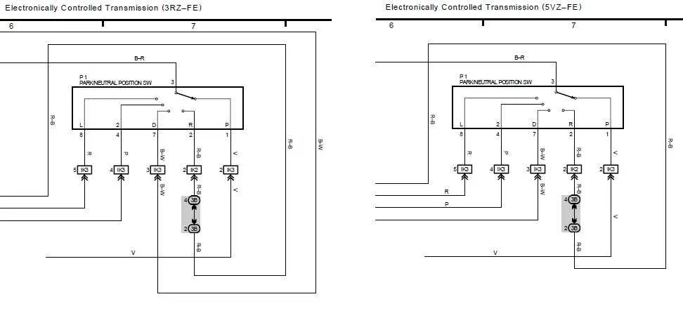
For a reliable connection of the transmission position sensor, follow this precise wiring guide:
- Connect the power source to the input terminal of the position sensor.
- Ensure the ground is securely attached to the designated grounding point to complete the circuit.
- Wire the output terminal to the control module, making sure it matches the required voltage levels.
- Use high-quality connectors to prevent poor connections or interference.
- Double-check for any short circuits before activation to avoid malfunctions.
Verify the sensor’s correct position before final installation to ensure proper operation when the transmission lever is in the correct gear. A faulty connection or improper wiring can cause shifting issues or even prevent the vehicle from starting in certain gears.
- Test continuity with a multimeter for all relevant wires to ensure they are intact and properly connected.
- Secure all connections with heat shrink tubing to protect against environmental factors.
- Inspect the sensor for proper alignment with the transmission lever to guarantee accurate readings.
How to Identify the Correct Wires for a Gear Selector Sensor
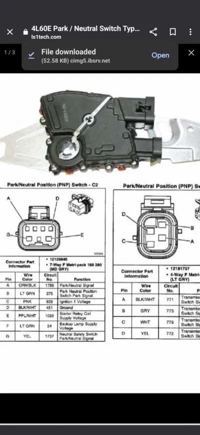
Begin by locating the sensor’s connection points, typically found near the gear shifter assembly. These terminals correspond to specific functions in the circuit.
Inspect the color-coding of the cables. Manufacturers often use standardized colors to differentiate the wires. Refer to the vehicle’s manual or service guide for the exact code specific to your model.
Check for the wire that connects to the ignition system. This is usually the one that gets power when the gear lever is in the park or neutral position. It’s vital to identify the power feed accurately to prevent miswiring.
Test continuity between the wires using a multimeter. The wire that completes the circuit when the shifter is in the correct position will be your functional wire. Ensure this wire shows no continuity in other gear positions.
Use a helper tool to determine which wire triggers the starter when the vehicle is in a non-park position. This is often a signal wire, and identifying it correctly ensures proper functioning when starting the engine.
| Wire Function | Color Code | Location |
|---|---|---|
| Ignition Signal | Red | Connector near gear shift |
| Starter Trigger | Green | Shifter mechanism |
| Ground | Black | Vehicle chassis |
For more accurate results, refer to a dedicated service manual for your vehicle model, as wire assignments can vary by manufacturer.
Step-by-Step Guide to Installing a Gear Position Sensor in Your Vehicle

Start by identifying the correct location for the sensor on your transmission. This component is usually mounted on the transmission casing or attached to the shift linkage. Consult your vehicle’s manual for specifics.
Next, disconnect the vehicle battery to avoid any electrical accidents while working. This step is crucial for your safety during installation.
Locate the wire harness connected to the sensor. You’ll need to disconnect the current wires before attaching the new ones. Make sure to document the original connections for reference during reinstallation.
Using appropriate connectors, link the sensor to the corresponding circuits in the vehicle’s electrical system. Ensure that the wiring connections are secure and protected from exposure to heat or moisture. Use insulating tape to cover any exposed wires to prevent potential short circuits.
Once the new wiring is in place, check the continuity using a multimeter to confirm that the connections are properly made and there are no faults in the circuit.
After confirming the electrical integrity, reinstall the gear position sensor and secure it in its mounting location. Tighten all bolts and ensure the component is securely attached to prevent any movement during operation.
Finally, reconnect the vehicle battery and test the operation of the gear indicator system. Shift through all gear positions and verify that the system responds correctly to each setting. If the vehicle functions as expected, the installation is complete.
Troubleshooting Common Issues with Gear Position Sensors

Start by checking for loose or corroded connections at the sensor terminals. A weak or intermittent connection can prevent proper function. Clean and tighten the contacts, ensuring a secure connection.
Next, inspect the wiring for visible damage or wear. Broken or frayed wires can disrupt signal transmission. Repair any damaged cables with high-quality connectors to restore continuity.
If the vehicle fails to start when in the correct gear, verify the continuity of the circuit leading to the control module. A malfunctioning module may fail to register the proper input from the gear position sensor. In such cases, replacing the module or testing with a multimeter can help confirm the issue.
Test the sensor itself by measuring its resistance across the terminals. Refer to the manufacturer’s specifications for correct resistance values. If the sensor does not meet the expected range, replace it.
If the system is still unresponsive, check for power supply issues. Ensure the fuse linked to the gear indicator system is intact and supplying power to the components. A blown fuse can cause the entire system to fail.
Lastly, verify the correct installation of the sensor and associated components. Misalignment or incorrect assembly can prevent the system from functioning as expected, even if all other parts are in working order.