Precise management of the liquid delivery system is crucial to maintaining consistent operation and preventing fluctuations that affect combustion efficiency. When examining the schematic of the device responsible for maintaining stable fluid flow, pay close attention to the connection points that influence the return line and the supply line. Proper routing of these connections ensures reliable operation and avoids malfunctions caused by incorrect assembly.
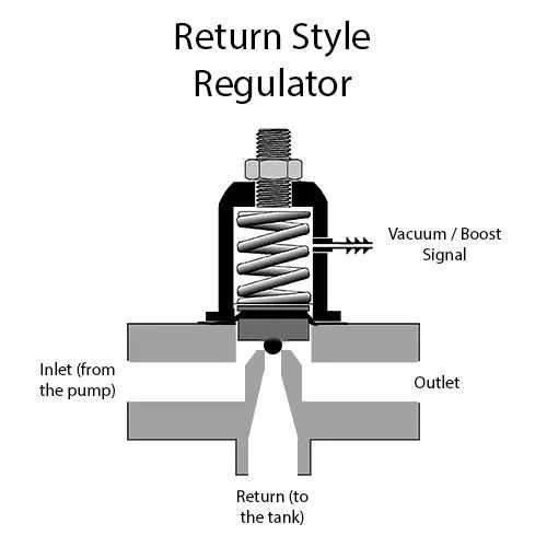
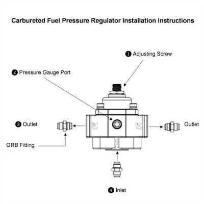
Key components include the diaphragm chamber, spring tension adjustment, and inlet/outlet ports. Mapping these elements with accurate wiring and tubing placement provides insight into how the system balances input and output forces to maintain a steady flow rate. Detailed schematics will highlight pressure sensing lines and feedback loops that control the valve’s opening degree.
For diagnostics and maintenance, prioritize identifying the correct terminals for signal input and vacuum lines. This layout enables technicians to measure variations effectively and adjust the tension settings to optimize the flow rate. Incorporating manufacturer-specific reference charts with these schematics supports precise calibration and troubleshooting.
Fuel Pressure Control System Layout

To ensure correct operation of the delivery system’s pressure controller, follow these wiring guidelines:
- Vacuum line connection: Connect the hose from the intake manifold directly to the diaphragm chamber to allow proper pressure adjustment based on engine load.
- Return line: Route the excess liquid flow back to the tank via a dedicated outlet port, preventing buildup in the delivery rail.
- Mounting position: Install the device at the same height as the delivery rail to avoid inaccurate readings caused by gravity or elevation differences.
- Electrical connector: For electronically controlled variants, ensure a secure connection to the engine control unit with proper pin alignment for signal transmission.
Typical mechanical layouts include:
- Input port from the pump assembly.
- Diaphragm chamber linked to vacuum source.
- Outlet to return line or tank.
- Pressure sensor output (if equipped).
Follow manufacturer’s technical drawings carefully to verify the hose routing and electrical wiring match your specific model. Deviations may result in unstable flow control or engine performance issues.
How to Identify Connections on the Schematic
Locate the component symbol often represented by a small round or rectangular shape with three terminals. One terminal typically connects to the supply line, another to the return line, and the third to a vacuum or control hose. These lines are usually labeled with abbreviations such as “IN,” “OUT,” and “VAC.”
Trace the line marked as “IN” or similar, which leads from the delivery side of the pump or rail. The “OUT” connection directs excess fluid back to the reservoir or tank. The vacuum or control port is linked to the intake manifold or an electronic control unit, depending on system type.
Verify terminal positions by cross-referencing adjacent components like sensors or valves; these will share wiring paths with the component in question. Look for annotations specifying operational values, such as psi or bar ratings near the component symbol.
Check for wiring color codes or pin numbers often indicated next to the terminals. These details aid in physical identification during troubleshooting or replacement tasks.
Interpreting Vacuum Lines and Flow Paths in the Schematic

Identify all vacuum hoses by tracing their connections to the intake manifold or vacuum source. These lines control the adjustment mechanism by responding to changes in manifold suction. A correctly routed vacuum tube will connect to the diaphragm chamber, influencing the control element based on engine load variations.
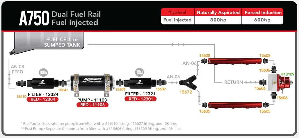
Examine the routing of the liquid delivery channels from the reservoir to the injectors and back to the return line. The path should show a smooth flow without unnecessary bends or blockages that might create turbulence or inconsistent delivery.
Note the presence of a reference hose linked to the intake manifold, which serves as a feedback line for maintaining stable operational output. This line balances the movement of the diaphragm against the system’s dynamic conditions.
Check for a return conduit leading excess liquid back to the tank or inlet side, preventing over-supply and ensuring continuous circulation. This loop stabilizes the system’s output and avoids fluctuations that could cause engine hesitation.
Confirm that all connectors are properly sealed and secured, as leaks in vacuum lines or delivery tubes directly affect performance by altering flow rates or causing unregulated pressure changes within the circuit.
Troubleshooting Common Issues Using the Control Valve Schematic
Start by verifying the reference line connections to ensure proper flow modulation. Incorrect routing often causes inconsistent delivery and fluctuating gauge readings. Measure the return line for blockages or kinks that may restrict flow, leading to abnormal output levels.
Check the diaphragm’s integrity by inspecting for cracks or tears that cause leaks or erratic response. Use the schematic to identify the test ports for direct measurement of operational values under varying loads. Comparing these values to manufacturer specifications helps isolate malfunctioning components.
Inspect the vacuum source linkage on the schematic to confirm proper attachment and no leaks. Loss of vacuum signal can result in unstable modulation and improper system balance. Employ a handheld gauge at the vacuum input indicated in the layout to verify consistent readings.
For electrical variants, follow the wiring layout carefully to detect shorts or open circuits. Confirm that the solenoid coils receive correct current by measuring voltage at the designated terminals. Faulty wiring or connectors often manifest as irregular output or system failure.
Utilize the schematic’s flow path indicators to trace fluid movement, ensuring no unintended bypasses or restrictions exist. Contamination or sediment build-up detected along these pathways frequently leads to sluggish response or erratic control.