
If you’re a guitar enthusiast or a lover of vintage sound, you’ve probably heard of the Firefly Amp. This highly sought-after amplifier has been praised for its ability to capture the rich, warm tones of classic rock and blues. But what exactly makes the Firefly Amp so special? In this article, we’ll take a closer look at the Firefly Amp schematic and explore how it brings vintage tone to the modern era.
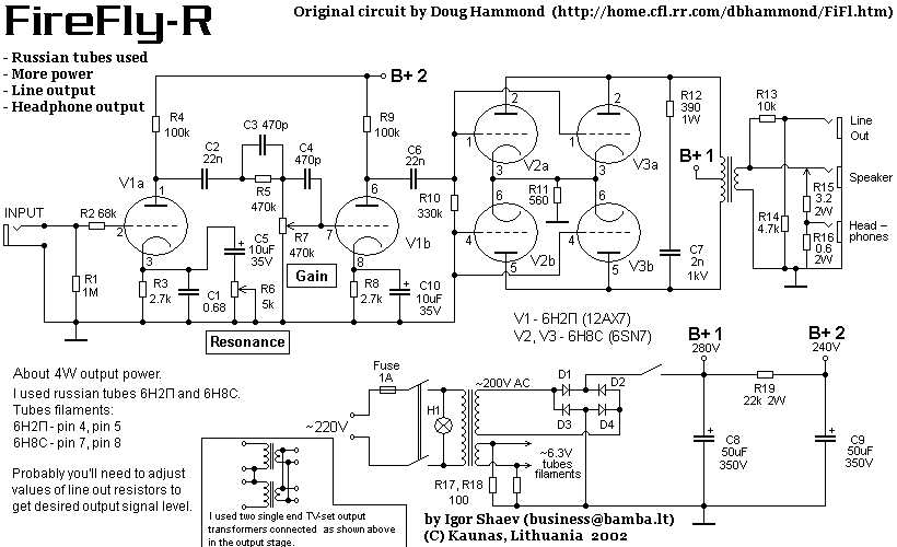
At the heart of the Firefly Amp is its meticulously designed schematic. This blueprint outlines the intricate circuitry and components that work together to produce the amp’s distinctive sound. From the choice of tubes and transformers to the arrangement of resistors and capacitors, every detail has been carefully considered to recreate the sonic characteristics of iconic amplifiers from the past.
One of the key features of the Firefly Amp schematic is its tube-driven preamp section. By using vacuum tubes to amplify the guitar signal, the amp is able to achieve a warm, organic tone that is reminiscent of the classic tube amps of the 1960s and 70s. The Firefly Amp also incorporates a unique tone stack design, allowing players to dial in a wide range of EQ settings to suit their playing style.
What is a Firefly Amp Schematic?
A firefly amp schematic is a diagram or blueprint that illustrates the electrical circuitry and components of a firefly amplifier. It provides a visual representation of how the different elements of the amplifier are interconnected and how the electrical signals flow within the circuit.
The firefly amp schematic typically includes symbols for various components such as resistors, capacitors, transistors, and integrated circuits. It also indicates the connections between these components, including the power supply, input and output jacks, and volume and tone controls.
Components:
- Resistors: These are passive electronic components that limit the flow of electric current within the circuit.
- Capacitors: These store and release electrical charge, helping to filter and smooth out the audio signal.
- Transistors: These are active electronic components that amplify the electrical signal, allowing for increased volume and distortion effects.
- Integrated circuits: These are complex electronic circuits housed in a single chip, often containing multiple transistors and other components.
Connections and Controls:
The firefly amp schematic shows how these components are connected, with lines indicating the flow of electrical current. It also illustrates the various input and output connections, such as the guitar input jack and speaker output jack.
The schematic may also include symbols for volume and tone controls, which allow the user to adjust the sound of the amplifier. These controls can affect the frequency response, dynamics, and overall tone of the amplifier.
Uses of Firefly Amp Schematic:
A firefly amp schematic is a valuable tool for guitarists, electronics enthusiasts, and technicians who work with amplifiers. It allows them to understand the inner workings of the amplifier and diagnose any issues or modify the circuit to achieve desired tonal characteristics.
With a firefly amp schematic, individuals can identify faulty components, troubleshoot problems, and make modifications or repairs. It is also useful for those interested in designing their own amplifiers or building custom amps from scratch.
Understanding the Basic Elements
In order to understand the Firefly amp schematic, it is important to familiarize oneself with the basic elements of the amplifier. These elements include the power supply, the preamp stage, the tone stack, the power amp section, and the output transformer.
Power Supply: The power supply is responsible for providing the necessary voltage and current to operate the amplifier. It typically consists of a transformer, rectifier, and filter capacitors.
Preamp Stage: The preamp stage is where the incoming signal is amplified and shaped. It often includes one or more vacuum tubes (also known as valves) and a variety of resistors, capacitors, and other components. The preamp stage is where the gain, EQ, and other tonal characteristics of the amplifier are controlled.
Tone Stack: The tone stack is a set of passive electronic filters that shape the frequency response of the amplifier. It typically includes controls for bass, midrange, and treble, allowing the user to adjust the overall tonal balance of the amplifier. The tone stack can have a significant impact on the overall sound of the amp.
Power Amp Section: The power amp section is responsible for amplifying the signal from the preamp stage to a level that can drive a speaker. It often includes one or more power tubes (such as EL34 or 6L6) and a phase inverter, which is used to drive the output transformer.
Output Transformer: The output transformer is a crucial part of the amp that matches the impedance of the power tubes to the speaker. It also provides isolation and impedance matching for the speaker, ensuring optimal power transfer and sound quality.
By understanding these basic elements, one can start to comprehend the Firefly amp schematic and how each component contributes to the overall sound and functionality of the amplifier.
Exploring the Different Components
When it comes to understanding the Firefly amp schematic, it’s important to familiarize yourself with the different components that make up the circuit. Each component plays a crucial role in shaping the sound and overall performance of the amplifier.
1. Power Supply:
The power supply is responsible for providing the necessary voltage and current for the amplifier to operate. In the Firefly amp schematic, you will find a power transformer that steps up the voltage from the wall outlet to a higher level. This higher voltage is then rectified and filtered to provide a stable DC voltage for the rest of the circuit.
2. Preamp Section:
The preamp section is where the tone shaping of the guitar signal begins. It typically consists of various stages, including a gain stage, tone control circuit, and volume control. The gain stage amplifies the guitar signal, while the tone control circuit adjusts the frequency response and EQ of the signal. The volume control allows you to adjust the overall output level of the preamp section.
3. Power Amp Section:
The power amp section is responsible for amplifying the preamp signal to a level that can drive the speaker. It usually consists of one or more power tubes that provide the necessary power and gain for the output stage. The power tubes are biased to operate in a specific region, which affects the overall tone and response of the amplifier.
4. Output Transformer:

When working with a Firefly amp, it is important to be aware of some common issues that may arise and how to troubleshoot them. This will help ensure optimal performance and prevent any potential damage to the amplifier.
One common issue that users may encounter is a lack of sound coming from the amplifier. This could be caused by a variety of factors, including a faulty cable connection, a blown fuse, or a problem with the speaker. To troubleshoot this issue, it is recommended to first check the cable connections and make sure they are securely plugged in. If the connections are fine, then checking the fuse is the next step. If the fuse is blown, it can be replaced with a new one of the same rating. If the issue persists, then it is recommended to check the speaker and ensure it is functioning properly.
Another common issue that users may face is a buzzing or humming noise coming from the amplifier. This can be caused by a few different factors, such as electromagnetic interference or a ground loop. To troubleshoot this issue, it is recommended to first check for any nearby electronic devices that could be causing interference. Moving the amplifier away from these devices or turning them off may help eliminate the noise. If the buzzing or humming noise persists, then it may be a ground loop issue. In this case, using a ground loop isolator can help eliminate the noise.
- No sound coming from the amplifier: Check cable connections, replace blown fuse, check speaker.
- Buzzing or humming noise: Check for electromagnetic interference, use ground loop isolator.
In addition to these specific issues, it is always recommended to regularly clean and maintain the Firefly amp to prevent any potential issues from arising. This includes dusting the amp, cleaning the connectors, and ensuring proper ventilation. Regular maintenance can help extend the lifespan of the amplifier and improve overall performance.
Benefits and Applications
The Firefly amp schematic offers a range of benefits and has various applications in the field of electronics. Here are some key advantages and common uses:
- Simplicity and Cost-effectiveness: The Firefly amp schematic is relatively simple and inexpensive to implement, making it an attractive option for DIY enthusiasts and electronics hobbyists.
- Compact Design: The schematic can be easily tailored to fit in small spaces, making it ideal for applications where size constraints are a consideration.
- Low Power Consumption: The Firefly amp schematic is designed to operate with low power consumption, which makes it suitable for portable electronic devices.
- High-Quality Sound: Despite its simplicity, the Firefly amp schematic can produce high-quality audio output, making it an excellent choice for audio-related applications.
- Wide Range of Applications: The Firefly amp schematic can be used in various applications such as guitar amplifiers, headphone amplifiers, audio distribution systems, and more. Its versatility makes it a popular choice among audio enthusiasts.
In conclusion, the Firefly amp schematic offers simplicity, cost-effectiveness, compact design, low power consumption, and high-quality sound. Its wide range of applications makes it a versatile choice for various electronic projects. Whether you are a DIY enthusiast, audio aficionado, or looking for an amplifier solution, the Firefly amp schematic can be a reliable and efficient option.