
In the world of electronics, circuits that involve flashing LEDs are quite popular. These circuits use a combination of resistors, capacitors, and transistors to drive an LED in a way that it alternately turns on and off, creating a flashing effect. The flashing LED circuit schematic provides a visual representation of how this circuit is wired and what components are used to achieve the desired effect.
The flashing LED circuit schematic typically includes symbols for the various components used in the circuit, such as resistors, capacitors, and transistors. It also indicates the polarity of the LED, as LEDs are directional and must be connected in the correct orientation to work properly. Additionally, the schematic may show the values of the resistors and capacitors used, as well as any other relevant details.
Flashing LEDs can be used in a variety of applications, from simple decorative lights to more complex signaling devices. The flashing LED circuit schematic provides a starting point for anyone wishing to build their own flashing LED circuit. By understanding the circuit diagram and the role of each component, electronics enthusiasts can customize the circuit to suit their specific needs and experiment with different flashing patterns and speeds.
Overall, the flashing LED circuit schematic serves as a guide for creating a circuit that produces a flashing effect using an LED. It provides a visual representation of the circuit and helps electronics enthusiasts understand how the various components work together to achieve the desired result. Whether you are a beginner in electronics or an experienced hobbyist, understanding and creating flashing LED circuits can be a rewarding and fun experience.
What is a Flashing LED Circuit Schematic?
A flashing LED circuit schematic is a design or diagram of an electronic circuit that controls the blinking or flashing of an LED (light-emitting diode). This schematic provides a visual representation of the components and connections needed to create a flashing LED circuit.
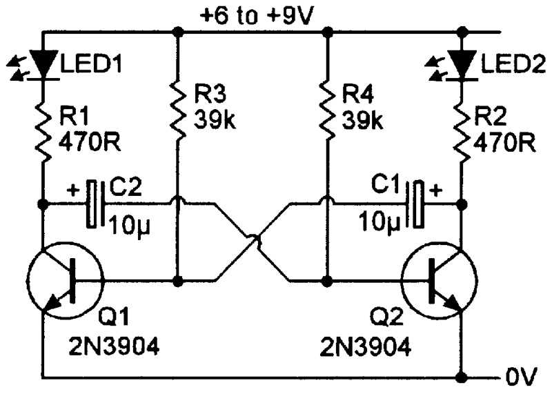
The flashing LED circuit schematic typically includes components such as resistors, capacitors, transistors, and the LED itself. These components work together to control the timing and frequency of the LED’s flashing pattern. The schematic shows how these components are connected, usually using lines and symbols to represent wires and electrical connections.
A flashing LED circuit schematic can be useful for hobbyists, students, or electronics enthusiasts who want to build their own flashing LED circuits. By following the schematic, they can understand how the circuit functions and how to assemble the necessary components. This can be a great way to learn about basic electronic principles and gain hands-on experience in circuit design and assembly.
There are many variations of flashing LED circuit schematics available, ranging from simple designs that use a few basic components to more complex circuits that incorporate microcontrollers or programmable chips. The choice of schematic will depend on the desired flashing pattern, complexity of the circuit, and the resources available.
Overall, a flashing LED circuit schematic is a valuable tool for understanding and creating circuits that produce a blinking or flashing light effect using an LED. Whether for educational purposes or practical applications, these schematics enable individuals to explore the world of electronics and create their own unique lighting effects.
Overview of Flashing LED Circuit Schematic
The flashing LED circuit schematic is a simple and widely used design that serves as an introduction to basic electronics and circuitry. This circuit utilizes a few components, including an LED, a resistor, and a capacitor, to create a flashing effect. It is commonly used in various applications, such as decorative lighting, warning signals, and educational projects.
The main components of the flashing LED circuit schematic are the LED and the resistor. The LED, or light-emitting diode, is a semiconductor device that emits light when an electric current is passed through it. It usually has two leads, with the longer lead being the positive (+) terminal and the shorter lead being the negative (-) terminal. The resistor is used to limit the amount of current flowing through the LED to prevent it from burning out.
In addition to the LED and the resistor, the flashing LED circuit schematic also includes a capacitor. The capacitor stores and releases electrical energy, which is essential for creating the flashing effect. The capacitor charges up when the circuit is first powered on and then discharges through the LED, causing it to light up. The cycle of charging and discharging repeats, resulting in a flashing effect.
To create the flashing LED circuit schematic, the components are connected in a specific configuration. The positive lead of the LED is connected to the positive terminal of the power source, while the negative lead is connected to one end of the resistor. The other end of the resistor is connected to one end of the capacitor. Finally, the negative terminal of the power source is connected to the other end of the capacitor.
The flashing LED circuit schematic is a great starting point for beginners to learn about basic electronic principles and circuit design. It is a fun and engaging project that can be easily built with readily available components. By understanding and experimenting with this circuit, individuals can gain hands-on experience and develop their skills in electronics.
Components Needed for Flashing LED Circuit Schematic
In order to create a flashing LED circuit schematic, there are several components that you will need. These components are essential for the circuit to function properly and produce the desired effect of a flashing LED.
Here are the components needed for a flashing LED circuit schematic:
- LED (Light Emitting Diode): The LED is the main component that emits light when an electric current is passed through it. It is usually available in different colors and is the focal point of the circuit.
- Resistor: A resistor is used to limit the amount of current flowing through the LED. It prevents the LED from burning out due to excessive current. The resistance value of the resistor depends on the LED forward voltage and desired current.
- Capacitor: A capacitor is used to store and release electrical energy in the circuit. It plays a crucial role in creating the flashing effect by controlling the timing and frequency of the LED pulses.
- Transistor: A transistor is an electronic component that amplifies or switches electronic signals and currents. It is commonly used in flashing LED circuits to control the flow of current to the LED.
- Power Source: A power source, such as a battery or power supply, is required to provide the necessary voltage and current for the circuit to operate. The voltage level depends on the specifications of the LED and other components.
- Connecting Wires: These wires are used to establish connections between the various components of the circuit. They ensure the flow of electrical signals and current from one component to another.
By assembling these components together according to a flashing LED circuit schematic diagram, you can create an electronic circuit that produces a flashing effect with the LED. The specific values and specifications of the components will vary depending on the desired flashing pattern and the requirements of the circuit.
Building the Flashing LED Circuit
To build the flashing LED circuit, you will need a few components: an LED (light-emitting diode), a resistor, a transistor, and a power source. The purpose of this circuit is to make the LED blink on and off at a regular interval, creating a flashing effect.
First, gather all the necessary components. Make sure you have the correct type of LED for your circuit and choose a resistor that will limit the current flowing through the LED. The transistor acts as a switch, allowing current to flow through the LED when it is in the “on” state. The power source provides the voltage for the circuit.
Begin by connecting one end of the resistor to the positive terminal of the power source. Connect the other end of the resistor to the base pin of the transistor. The base pin is usually denoted with a letter, such as “B”. Then, connect the emitter pin of the transistor to the negative terminal of the power source. Finally, connect the collector pin of the transistor to the positive terminal of the LED. Connect the negative terminal of the LED to the negative terminal of the power source.
The LED should now start flashing on and off at a regular interval. The blinking speed can be adjusted by changing the values of the resistor and capacitor in the circuit. Experiment with different values to achieve the desired flashing effect. Remember to always use the appropriate safety precautions when working with electrical circuits.
Understanding the Working of Flashing LED Circuit

Flashing LED circuits are a popular choice for various electronic projects and designs, as they add visual effects and attract attention. These circuits are widely used in toys, decorative lighting, safety devices, and many other applications. Understanding how a flashing LED circuit works can help in designing and troubleshooting electronic projects.
A flashing LED circuit typically consists of an LED, a resistor, a capacitor, and a transistor or an integrated circuit (IC). The components are connected in such a way that the LED turns on and off repeatedly, creating a flashing effect. The timing of the flashing can be controlled by adjusting the values of the resistor and capacitor or by using specific timing devices.
The basic principle behind the flashing LED circuit is the charging and discharging of the capacitor. When the circuit is powered on, the capacitor starts to charge through the resistor, building up voltage. Once the voltage across the capacitor reaches a certain threshold, it triggers the transistor or IC, allowing current to flow through the LED. As the capacitor discharges, the voltage across it decreases, eventually reaching a point where it can no longer keep the transistor or IC in the “on” state. This turns off the LED and the cycle repeats.
By adjusting the values of the resistor and capacitor, the flashing rate of the LED can be changed. A smaller resistor or larger capacitor will result in slower flashing, while a larger resistor or smaller capacitor will result in faster flashing. This allows for customization of the flashing effect based on the desired application.
In some circuits, additional components like diodes or transistors may be added to enhance the performance or control the flashing pattern. These circuits can vary in complexity depending on the desired functionality. However, the basic principle of charging and discharging the capacitor remains the same.
In conclusion, understanding the working of a flashing LED circuit involves grasping the concept of charging and discharging a capacitor to control the on-off cycle of the LED. With this understanding, one can design and troubleshoot various electronic projects that incorporate flashing LED effects.
Troubleshooting and Tips for Flashing LED Circuit
If you are experiencing issues with your flashing LED circuit or you’re just looking for some tips to make it work more efficiently, you’ve come to the right place. Here are some common troubleshooting solutions and useful tips to help you:
Troubleshooting:

- Check the connections: Ensure that all the components in your circuit are properly connected. Loose or incorrect connections can cause the LED to not flash or behave unexpectedly. Double-check all the connections and make sure they are secure.
- Verify component values: Ensure that you are using the correct values for resistors, capacitors, and other components in your circuit. Using incorrect values can affect the flashing frequency or prevent the LED from flashing at all.
- Test individual components: If you suspect that a particular component may be faulty, test it separately to confirm its functionality. This can be done using a multimeter or by substituting the component with a known working one.
- Check for damaged components: Inspect all the components for any signs of physical damage, such as burnt or cracked components. Replace any damaged components to ensure proper functioning of the circuit.
- Inspect the solder joints: Examine the solder joints on the circuit board. Cold or weak solder joints can cause intermittent or unreliable connections. Resolder any suspect joints to ensure good electrical contact.
Tips:

- Use appropriate power supply: Ensure that you are using the correct power supply voltage for your circuit. Applying excessive voltage can damage the components, while insufficient voltage may prevent the circuit from functioning.
- Use high-quality components: Using high-quality components can improve the reliability and performance of your flashing LED circuit. Opt for components from reputable manufacturers and suppliers.
- Experiment with different component values: To achieve different flashing patterns or frequencies, try experimenting with different resistor and capacitor values. This can help you customize the flashing effect according to your requirements.
- Add a current-limiting resistor: To protect the LED from excessive current and prevent damage, consider adding a current-limiting resistor in series with the LED. Refer to the LED datasheet for the appropriate resistor value.
- Document your circuit: Keep a record of your circuit schematic and any modifications or adjustments you make. This documentation will be helpful for troubleshooting in the future or when replicating the circuit.
By following these troubleshooting tips and utilizing the suggested techniques, you should be able to diagnose and resolve any issues with your flashing LED circuit. Remember to be patient and thorough in your troubleshooting process. Happy circuit building!