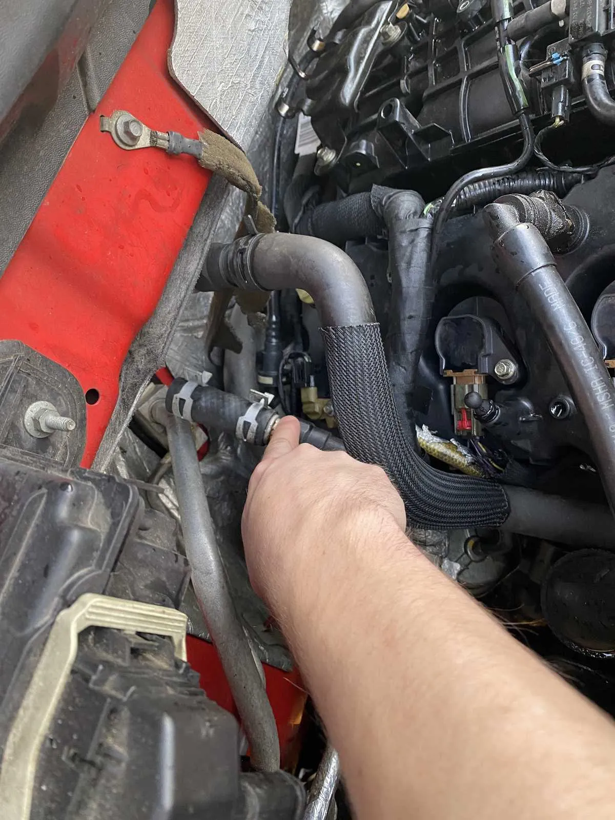
Begin by replacing the flexible coolant conduit between the engine block outlet and the firewall connection. Order the OEM part numbers 7L3Z-18472-A (upper supply tube) and 7L3Z-18472-B (lower return tube) to guarantee an exact fit. Ensure the direction of flow runs from the cylinder head port toward the bulkhead fitting.
On removal, loosen the spring clamps at positions “A” and “B,” then disengage the conduit from the manifold bracket. Retain the original O-rings if they remain pliable; otherwise, install new seals (Motorcraft SW-637). Torque the banjo-style fittings to 80 in-lb to prevent leaks.
After assembly, perform a system flush with a 50/50 ethylene glycol solution at 120 °F. Route the new tubing around the front exhaust crossover, securing it with retainer clips spaced no more than 4 inches apart. Verify there are no kinks or torsion in the flexible lines before pressurizing to 15 psi for the final leak check.
Large-Displacement V8 Cabin Warmer Tube Schematic
Connect the inlet conduit from the pump outlet directly to the matrix feed port at the firewall before routing the return line back to the intake manifold bypass valve.
- Inlet conduit: 12 mm reinforced rubber, links pump outlet to core feed nipple.
- Return conduit: 8 mm nylon-reinforced tube, runs from core exit to block bypass fitting.
- Clamps: stainless spring type, torque to 4.5 Nm.
- Release spring clip on passenger-side head port.
- Route 12 mm feed tube beneath alternator bracket, avoiding contact with pulleys.
- Attach 8 mm return line to lower intake bypass nipple; secure with spring clamp.
- Verify unrestricted flow by gently squeezing inlet conduit; coolant should circulate freely.
Service schedule: replace both lines every 10 years or every 160,000 miles; inspect clamps annually to prevent steam leaks.
Identifying the Primary Coolant Line Connections on the Modular V8 Platform
Install a 5/8″ inner-diameter EPDM tubing between the thermostat outlet and the bulkhead adapter to ensure optimal flow; secure each junction with stainless-steel worm-drive clamps torqued to 2.5 Nm.
Locate the inlet fitting on the cylinder-head near the driver-side exhaust manifold–this serves as the feed point. The return port sits at the firewall-mounted valve assembly; confirm the quick-disconnect clip engages fully and the internal O-ring is free of cracks.
Route the supply line above the frame-rail crossmember and away from thermal sources, maintaining a 1 cm clearance from the exhaust wrap; use ribbed P-clips at 30 cm spacing to prevent chafing and vibration fatigue.
Verify the bypass circuit link from the water-pump housing to the intake plenum: this smaller 3/8″ tube stabilizes cabin circulation during cold starts. Replace aged lines every 100 000 km to avoid coolant leaks and maintain cabin comfort.
Routing Path and Mounting Points of the Warming Circuit Conduits in the 330ci V8 Platform
Position the inlet cooling line from the block’s passenger-side port to the firewall passage just above the transmission hump, keeping it parallel to the cabin floor and secured by two spring-steel clips at the carpet edge.
Route the return tubing from the dashboard bulkhead fitting forward beneath the dash assembly, threading it behind the blower motor housing; anchor it at the firewall using the factory-installed bracket on the driver’s side stud and a rubber-insulated clamp on the heater box mounting bolt.
Avoid routing any section near the down-pipe by maintaining a 50 mm clearance; use the molded plastic guide clip on the front crossmember to prevent chafing against the sway-bar link.
Ensure all tubing connections use 20–25 lb worm-drive clamps torqued to 5 Nm; inspect the P-clip at the radiator support and replace if cracked to maintain correct alignment and prevent vibration wear.
Common Leak Locations and Line Replacement Tips for the Triton V8 Thermal Loop
Prioritize inspection of the upper flexible coolant line where it connects to the plastic intake manifold: cracks often develop at the crimped ferrules after 80,000 miles, especially if operating temperatures exceed 240 °F.
Check the lower connection at the water distribution block behind the wheel well for swelling or oil contamination; replace with an OEM-style EPDM assembly rated to 40 psi and secure with clip-style clamps torqued to 24 in·lb.
At each maintenance interval, perform a pressure drop test on the dash core inlet at the firewall– a loss greater than 2 psi over 5 minutes signals an internal split. Substitute with a reinforced silicone unit capable of withstanding 275 °F.
During installation, apply a thin bead of high-temperature sealant on each male barb, orient clamps 180° apart, then verify circuit integrity by holding 15 psi for at least 30 seconds with a handheld tester.