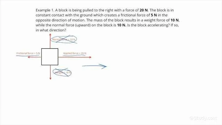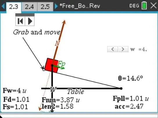
To visualize physical forces and their directions in a system, use an interactive tool that allows you to draw precise representations. These tools enable you to input data on applied forces, moments, and other relevant variables, providing clear illustrations. Begin by choosing a reliable platform that allows detailed customization for each force vector, ensuring clarity in your schematic. Pay close attention to the ability to adjust the magnitude, direction, and points of application for each force to capture the system’s behavior accurately.
Consider utilizing software with a simple interface that focuses on intuitive design and quick adjustments. A tool with drag-and-drop functionality lets you arrange forces without hassle, ensuring speed and accuracy. Additionally, ensure that the platform offers the option to label and annotate each vector for better clarity, especially when sharing the image with others for review or collaboration.
Once the illustration is complete, be sure to check the scale and units of measurement to avoid inconsistencies. The software should allow you to adjust scale settings according to your system’s requirements. An ideal solution will offer options for exporting your representation into formats suitable for further analysis or presentations, such as PDF or PNG files.
Creating Accurate Force Sketches Online

Utilize advanced online tools to quickly produce precise visual representations of forces acting on an object. These tools allow you to easily place vectors representing forces, moments, and constraints, making complex mechanical analysis simpler. Choose platforms that support various inputs like angles, magnitudes, and directions to tailor the illustration to your needs.
Look for features such as real-time updates when adjusting variables, which ensures that the model reflects changes immediately. Additionally, certain tools allow exporting your work in different formats, ensuring compatibility with your engineering software. These platforms also often include options for customizing the scale and orientation of forces for clearer visual clarity.
Opt for solutions that offer built-in libraries of common objects, such as beams, pulleys, or springs, to speed up the drawing process. This can significantly reduce the time spent creating the visual representation, especially for repetitive tasks. Moreover, many offer intuitive drag-and-drop features, making them accessible even for beginners.
For more accuracy, always verify that the software lets you input specific data like angles and forces directly, rather than relying on freehand adjustments. Integration with calculation tools can further enhance the precision of your model, ensuring you can transition seamlessly from visual to numerical analysis.
How to Create Accurate Force Diagrams Using Online Tools
Start by selecting a reliable online tool designed for structural analysis. These platforms allow precise visualization of forces acting on objects, simplifying the modeling process. Choose one that offers clear input options for defining forces, moments, and constraints. Some tools have drag-and-drop interfaces, which make the process intuitive.
Ensure that all elements are properly labeled and that the coordinate system is correctly set. This is crucial for maintaining consistency and accuracy, especially when dealing with multiple interactions. Use the grid or reference points provided by the tool to position each force vector precisely.
When inputting forces, define both magnitude and direction. Most online platforms allow you to input values directly or manipulate vectors interactively. Pay attention to the units, and verify that they match the system being used in your calculations (e.g., Newtons for force, meters for distance). If available, enable features like automatic force summation or moment calculation to cross-check your results.
Double-check the physical assumptions made by the tool. Ensure that it accounts for constraints like fixed supports, rollers, or hinges, and applies the correct boundary conditions for each type of interaction. Some advanced tools even offer simulation modes that visualize how forces change as conditions are altered.
Finally, after building the setup, use the tool’s analysis features to run simulations. These will help you identify any imbalances or incorrect assumptions. Output data from the tool can be further analyzed or imported into other programs for more advanced calculations. Save your work in various formats to allow for easy sharing or modification later.
Common Errors to Avoid When Using Force Representation Tools
Ensure that all applied forces are correctly represented in terms of direction and magnitude. Misplacing vectors or using incorrect angles can lead to inaccurate results.
Pay attention to scale when drawing forces. Often, users fail to scale vectors proportionally, which can cause errors in the calculation of resultant forces and moments.
Verify the point of application for each force. Incorrectly positioning forces relative to the object can alter the response and lead to invalid conclusions regarding equilibrium or motion.
Do not overlook friction and other resistive forces. Ignoring these elements, especially in static scenarios, may result in oversimplifications that undermine the analysis.
Check for consistency in units. Mixing units (e.g., Newtons with pounds) can distort the overall calculations and lead to significant inaccuracies.
Double-check boundary conditions, such as supports or constraints, to ensure they are accurately depicted. Incorrect assumptions about fixed or movable points can lead to incorrect predictions of stress or deformation.
When multiple objects are involved, make sure to distinguish between forces acting on each object clearly. Misinterpreting the interaction forces between components can lead to incorrect assessments of the system’s behavior.
Best Tools for Visualizing Mechanical Forces in Engineering
For engineering students looking for efficient ways to visualize forces and moments acting on structures or objects, these tools provide the best solutions:
- Draw.io – A versatile web tool that allows users to create clear representations of mechanical systems. It offers an intuitive drag-and-drop interface with plenty of templates and customization options for different engineering problems.
- GeoGebra – Known for its interactive mathematical capabilities, GeoGebra can be used to model forces and motion in 2D or 3D, making it a great resource for visualizing static and dynamic systems.
- SolidWorks – Although primarily a 3D CAD tool, SolidWorks allows users to simulate forces in mechanical systems and visualize the results through intuitive animations and analysis tools.
- SketchUp – While SketchUp is a general design tool, its flexibility and ease of use make it suitable for visualizing force interactions in basic engineering scenarios.
- PhET Interactive Simulations – This platform offers engaging simulations for force and motion, particularly useful for students who need to understand how forces impact objects in real-time scenarios.
These tools cater to different levels of complexity and specific needs, making them highly recommended for engineering students working on visualizing mechanical principles.