Start by checking the underside of the driver’s side dashboard–this is where most current-routing components are grouped. Remove the plastic panel by pulling firmly along the edges. You’ll see a black enclosure with a removable cover. Inside, you’ll find a labeled chart molded into the lid. Use this chart to match circuit numbers with their corresponding accessories.
If the horn, radio, or power windows stop working, inspect the matching current-protection element in this cluster. Each unit is color-coded by amperage: red (10A), blue (15A), yellow (20A), and so on. Use needle-nose pliers to remove any suspect piece and check the internal metal strip. If broken, replace it with one of the same rating.
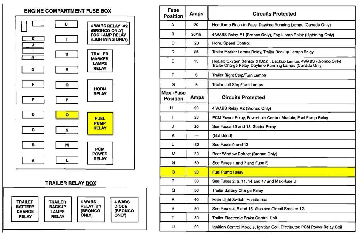
For lighting-related issues, there’s a second module beneath the hood on the driver’s side. This weather-sealed box manages higher-load systems like headlights, trailer connections, and the ignition relay. Release the latches, lift the cover, and refer to the placement guide stamped inside. Avoid swapping components randomly; always compare part numbers before replacing relays or larger units.
When testing, disconnect the battery to avoid shorts. After replacement, restore power and verify function. If problems persist, inspect related wiring and grounding points. Electrical continuity testers or multimeters can help isolate faults beyond the panel itself.
Main Panel Layout and Element Functions
Locate the primary electrical board under the driver-side dashboard panel. Use a flashlight to clearly identify each labeled slot.
- Position 1: Manages the radio and audio system. Replace with a 15A mini blade unit.
- Slot 2: Linked to interior lamps and the dome circuit. 10A red unit required.
- Point 4: Controls the power mirrors. Standard 7.5A brown unit fits here.
- Row 6: Dedicated to the instrument cluster and warning lights. 15A blue required.
- Spot 9: Serves the cigarette lighter and accessory ports. Uses a 20A yellow component.
Always match the amperage and color coding when replacing any element. Disconnect the battery before handling the system to avoid shorts or shocks.
Fuse Box Locations and Access Points in the 2001 Ford F150
Start by checking beneath the dashboard on the driver’s side. The primary power distribution block is mounted above the brake pedal. To reach it, release the latch on the small panel cover and pull it outward. No tools are needed for this step.
The secondary unit is placed under the hood, on the left side near the battery. Open the hood and locate a black rectangular casing with a snap-on lid. Press the clips on both sides to remove the cover. Always disconnect the battery before working here to avoid electrical shorts.
In extended cab variants, there may be an auxiliary block behind the passenger kick panel. Remove the trim by unscrewing two fasteners at the base, then pull the panel away gently to reveal the module behind the carpeting.
For each location, use a flashlight to inspect labels or etched codes next to each slot. These markings help match components like lighting, blower motors, or signal relays to their corresponding slot. When replacing a blown element, match both the amperage and size to avoid system damage.
Detailed Fuse Assignments for the Under-Dash and Under-Hood Panels

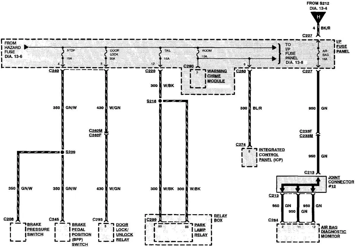
Cabin Power Distribution Panel: Position 1 powers the left turn signal and warning chime. Slot 2 supplies current to the right turn indicator and airbag module. Location 5 is linked to the instrument cluster backlighting. Circuit 6 provides energy to the brake pedal switch and shift interlock system. Terminal 13 handles the windshield wiper motor. Contact 16 supports the radio and auxiliary power point. Port 20 routes electricity to the diagnostic connector and electronic control unit.
Engine Bay Relay Center: Slot 1 activates the blower motor relay. Section 2 supports the fuel pump control. Area 3 is connected to the PCM power relay. Contact 4 energizes the horn circuit. Position 6 feeds the air conditioning clutch. Location 8 supplies power to the trailer tow backup lamps. Terminal 10 handles current for the alternator field input and voltage regulator. Section 14 supports ABS hydraulic unit and control module. Area 16 is linked to the headlamp relays and DRL (if equipped).
Always verify amperage values and wiring layout before replacing any protective component. Use the owner’s manual or printed label on the access cover as a quick reference.
How to Identify and Replace a Blown Circuit Protector in This Pickup Model

Start by checking the cabin-mounted relay panel beneath the steering wheel. Locate the affected circuit by matching the system that’s malfunctioning–like the radio, power windows, or tail lights–with its corresponding slot using the label on the panel cover.
Once the suspect slot is found, pull the mini protector using needle-nose pliers or a plastic puller. Inspect the metal strip inside. A visible break or discoloration confirms failure.
Use only the same amperage rating when inserting a replacement. The rating is embossed on the plastic housing–common values include 10A (red), 15A (blue), or 20A (yellow). Never substitute with a higher rating, as this risks wiring damage or fire.
After inserting the new component, test the associated system. If the issue persists or the new unit fails immediately, there may be a short circuit or faulty load device requiring further diagnosis.
Under-hood slots, housed near the battery, follow the same replacement process. These protect critical components like the ignition, fuel system, and cooling fans. Always disconnect the negative battery terminal before working in this section to prevent accidental shorts.