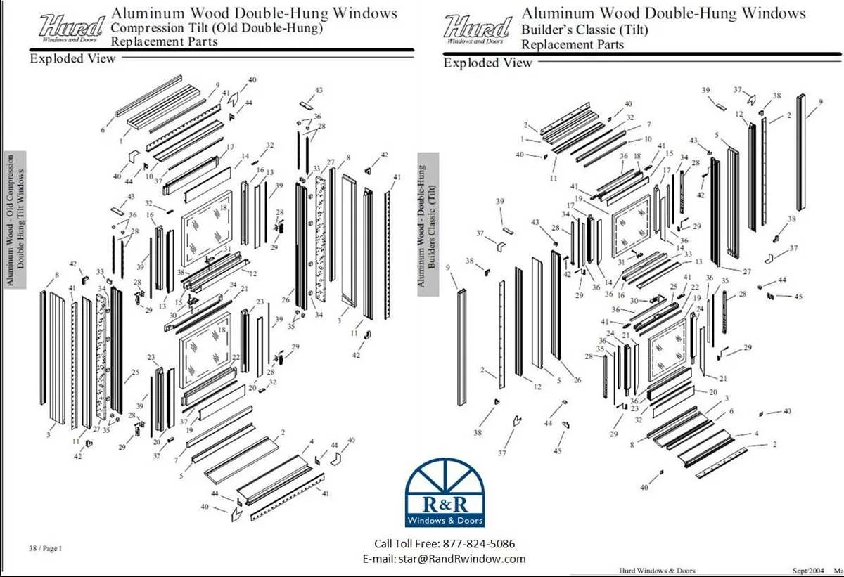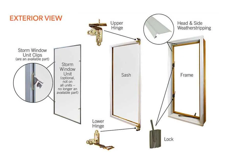
To ensure efficient repair or upgrade of your casement assembly, understanding the detailed schematic of each element is crucial. Familiarize yourself with the individual segments such as sashes, glazing beads, locks, and hinges to facilitate precise ordering and installation.
Accurate identification of structural pieces and their relative positioning minimizes errors during maintenance and helps avoid unnecessary costs. Consult detailed illustrations that clearly mark each element to comprehend their function and interaction within the overall assembly.
Pay special attention to fastening mechanisms and sealing strips, as these influence both security and insulation quality. Knowing how these components integrate allows for seamless substitution and prolongs the lifespan of the entire fixture.
Referencing comprehensive layouts aids in troubleshooting operational issues and supports effective communication with suppliers or technicians. A well-documented breakdown of all segments improves both the efficiency and accuracy of the restoration process.
Essential Components Illustration for Pane Units
Identify the sash frame first, as it holds the glass securely and allows smooth operation. Next, locate the balance mechanism, often a spring or weight system, responsible for counterbalancing the sash’s weight. The locking hardware ensures the sash stays firmly shut, preventing drafts and enhancing security.
Inspect the glazing bead, which clamps the glass into place within the sash. Weatherstripping should run along the perimeter to seal gaps and improve insulation. Check the jamb liners that facilitate effortless sliding motion along the track channels embedded in the frame.
For tilt-in models, note the tilt latch assembly that allows the sash to pivot inward for cleaning. The sill track at the base collects condensation and provides drainage. Understanding the relationship and placement of these components streamlines troubleshooting and efficient replacements.
Identifying Common Components in Replacement Window Diagrams
Start by locating the frame assembly, which forms the structural base for the entire unit. This usually includes the head, jambs, and sill. Each segment is clearly marked to help distinguish load-bearing sections from movable parts.
Next, focus on the sash elements–these are the operable sections that hold the glass panes. Commonly, they consist of the sash rails and stiles, which provide support and shape. Pay attention to any locking mechanisms or tilt latches integrated into these components.
Check the glazing components, such as glass panes and glazing beads. These are often illustrated separately to highlight their removable or replaceable nature. The glazing beads secure the glass in place and may vary in style depending on the model.
Inspect the hardware elements including hinges, handles, and locking systems. These small but crucial parts ensure functionality and security. Diagrams typically label these items with part numbers or codes for easy ordering.
Sealants and weatherstripping are usually indicated along the perimeter of the frame and sash. Identifying these materials is vital for maintaining insulation and preventing drafts.
Understanding the placement and interaction of these components facilitates accurate identification and efficient repairs or upgrades.
How to Use Schematics for Accurate Component Ordering
Always start by identifying the exact model number and manufacturing date of your unit before consulting any technical illustration. This ensures compatibility and precision in selecting the necessary element.
- Locate the reference codes: Each segment in the schematic is usually marked with a unique identifier or code. Note these carefully, as suppliers require them for accurate retrieval.
- Cross-check item descriptions: Compare the labels from the illustration with the parts list or catalog to confirm dimensions, materials, and specifications.
- Measure original components: If possible, verify sizes and fitting details physically to avoid ordering incompatible replacements.
- Consult legend or key: Utilize the legend accompanying the technical sketch to understand symbols and notations that indicate part functions or installation methods.
- Verify quantity and variants: Confirm how many units of each component are needed and check for different versions or configurations shown in the schematic.
Adopting this methodical approach minimizes errors, speeds up procurement, and guarantees that all ordered elements fit seamlessly into your assembly.
Troubleshooting Issues Using Component Schematics

Identify the faulty element precisely by consulting the schematic layout to locate each segment’s position and function. This allows targeted inspection of hardware like hinges, locks, seals, or sliding tracks without guesswork.
Check alignment problems by comparing the current installation with the technical illustration. Misplaced guides or worn-out rollers often cause sticking or difficulty in operation and are clearly marked in the schematic.
Inspect sealing components such as gaskets or weatherstrips shown in the reference layout. Damaged or compressed seals lead to drafts or moisture ingress and should be replaced according to the exact specification from the schematic.
Evaluate mechanical fasteners and connectors detailed in the blueprint for looseness or corrosion. Re-tightening or substituting screws and brackets prevents rattling and improves structural stability.
Utilize part codes and labels found in the schematic to order precise replacements or compatible substitutes, ensuring functional integrity and ease of installation.
Refer to sectional views for understanding complex assemblies, enabling effective dismantling and reassembly during maintenance or repairs.