
If you are a motorcycle enthusiast and own a Gy6 scooter, it’s important to understand the different electrical components that make up your scooter’s electrical system. One vital component is the voltage regulator, which plays a crucial role in regulating the voltage output from the scooter’s charging system. In this article, we will discuss the wiring diagram for the Gy6 voltage regulator and how it connects to the various electrical components of your scooter.
The voltage regulator is responsible for maintaining a stable voltage output to ensure that all the electrical components in your scooter receive the correct amount of power. Without a properly functioning voltage regulator, your scooter’s battery could become overcharged or undercharged, leading to starting and performance issues. Understanding how the voltage regulator is wired and connected will help you troubleshoot any electrical problems you may encounter in the future.
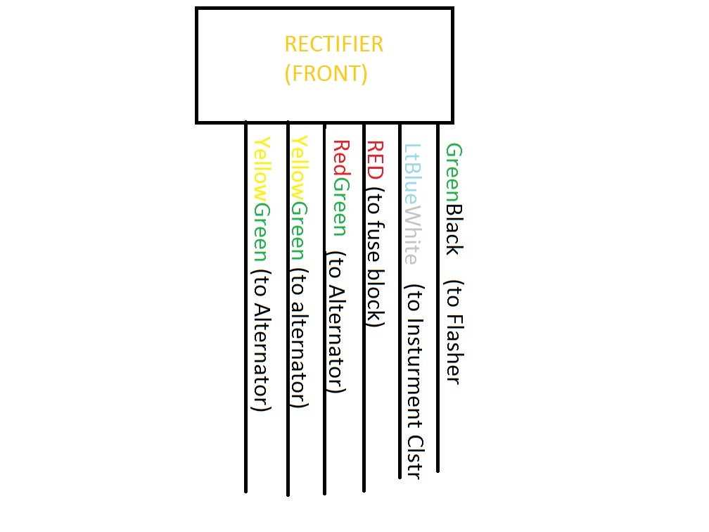
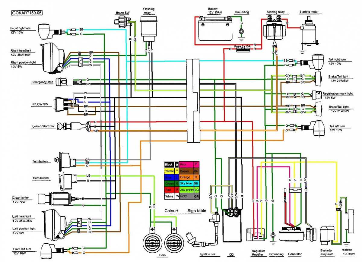
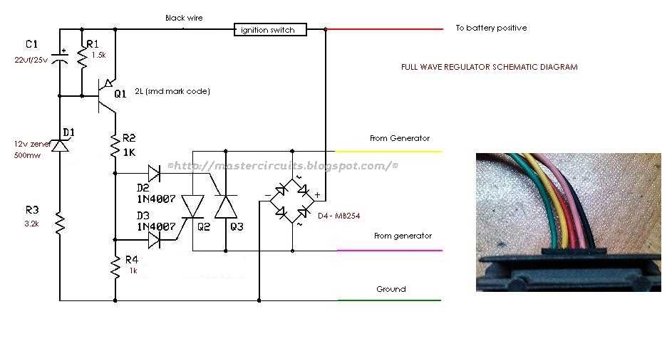
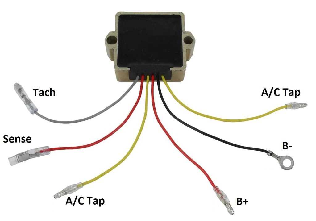
The wiring diagram for the Gy6 voltage regulator consists of various colored wires that connect to different parts of the scooter’s electrical system. These wires include the yellow wire, which connects to the stator source coil, the red wire, which connects to the battery positive terminal, and the black wire, which connects to the common ground. Additionally, there may be other wires such as the green wire, which connects to the ignition system, and the blue or white wire, which connects to the lighting system.
By following the Gy6 voltage regulator wiring diagram, you can easily identify the correct connection points and ensure that your scooter’s electrical system is functioning properly. If you ever need to replace or troubleshoot your scooter’s voltage regulator, having a clear understanding of the wiring diagram will prove to be invaluable. Remember, safety is paramount, so always ensure that you are working with the scooter’s electrical system when the engine is off and the battery is disconnected.
Gy6 Voltage Regulator Wiring Diagram
The Gy6 voltage regulator is an important component in a Gy6 engine system. It is responsible for regulating the voltage from the generator to the battery and other electrical components. Without a properly functioning voltage regulator, the electrical system of the engine can become unstable and may result in damage to the battery or other electrical components.
Wiring diagram:
The wiring diagram for the Gy6 voltage regulator consists of several components and connections. Here is a brief explanation of the different parts:
- Generator: This is the source of electrical power in the engine. It produces an alternating current (AC) that needs to be converted into direct current (DC) by the voltage regulator.
- Voltage regulator: This is the main component of the wiring diagram. It regulates the voltage output from the generator and ensures that it is within the acceptable range for the battery and other electrical components.
- Battery: The battery stores and supplies electrical power to the various components of the engine.
- Ignition switch: This switch controls the flow of electrical power to the engine’s ignition system.
- Starter solenoid: The starter solenoid is responsible for engaging the starter motor when the ignition switch is turned on.
- Starter motor: The starter motor is used to start the engine by turning the crankshaft.
The wiring diagram shows the connections between these components and the correct wiring sequence. It is important to follow the diagram closely to ensure proper installation and operation of the Gy6 voltage regulator. Any incorrect wiring could result in damage to the electrical system or other engine components.
Overall, the Gy6 voltage regulator wiring diagram is a crucial resource for anyone working on a Gy6 engine system. It provides a visual guide to the correct wiring connections and ensures that the electrical system operates safely and efficiently.
What is a Voltage Regulator?
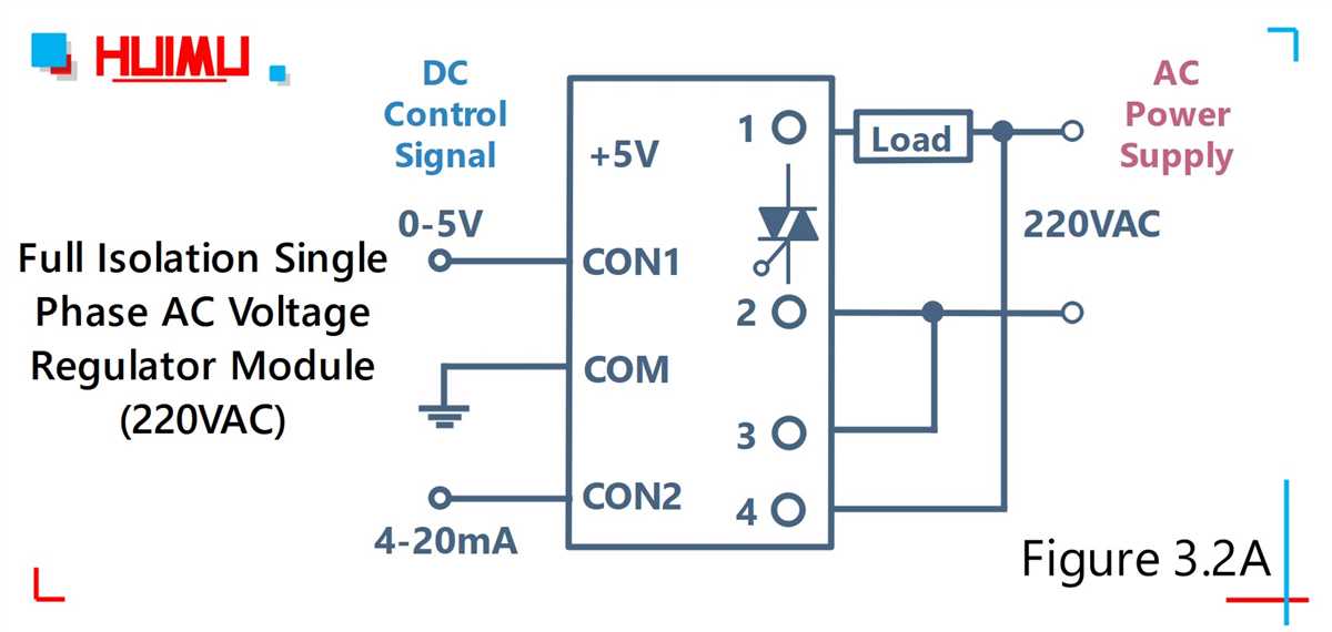
A voltage regulator is an electrical device that controls the voltage output of a power supply. Its primary function is to maintain a stable and constant voltage level regardless of changes in input voltage or load variations. Voltage regulators are commonly used in various electronic devices and power systems to ensure the reliable and efficient operation of electrical components.
There are different types of voltage regulators, including linear regulators and switching regulators. Linear regulators work by dissipating excess voltage as heat, while switching regulators use a more efficient technique to convert the input voltage into a regulated output voltage.
One of the key applications of voltage regulators is to protect sensitive electronic components from voltage fluctuations that could potentially damage them. By maintaining a stable voltage level, a voltage regulator helps prevent overvoltage and undervoltage conditions, ensuring that the electrical devices receive the correct voltage they require to function properly.
Furthermore, voltage regulators also play a crucial role in power distribution systems, where they help regulate the voltage levels across the electrical grid. This ensures that the voltage supplied to households and businesses remains within the acceptable range, preventing damage to appliances and equipment.
Overall, voltage regulators are essential components in ensuring the stability and reliability of electrical systems. Whether it’s in electronic devices or power distribution systems, these regulators help maintain a consistent voltage level, protecting equipment and ensuring optimal performance.
Why is a Voltage Regulator Important in a Gy6 Engine?
A voltage regulator is an essential component in a Gy6 engine because it ensures a stable and reliable supply of electrical power to the various parts and systems of the engine. The voltage regulator controls the amount of voltage produced by the engine’s alternator, which is responsible for generating electricity. Without a voltage regulator, the electrical components in the engine may receive an inconsistent or excessive amount of voltage, leading to various issues and potential damage.
The voltage regulator in a Gy6 engine helps maintain a constant voltage output, typically around 14 volts, regardless of the engine’s RPM or load. This ensures that all electrical components, such as the ignition system, fuel injection system, and lights, receive the appropriate amount of power to function optimally. Moreover, by regulating the voltage, the voltage regulator protects the components from excessive voltage spikes that can occur during sudden changes in load or when starting the engine.
The wiring diagram for a Gy6 voltage regulator typically includes connections to the alternator, battery, and various electrical components. It is crucial to follow the correct wiring diagram to ensure proper installation and functioning of the voltage regulator. This diagram can help identify the correct terminals and connections for each wire, preventing any mistakes that could lead to electrical issues or component failure.
In conclusion, a voltage regulator plays a vital role in a Gy6 engine by stabilizing and controlling the amount of voltage produced by the alternator. It ensures a reliable power supply to the engine’s electrical components, preventing damage and optimizing their performance. Following the appropriate wiring diagram is crucial for correct installation and proper functioning of the voltage regulator.
Understanding the Wiring Diagram
The wiring diagram for a Gy6 voltage regulator is an essential tool in understanding how the electrical system of a Gy6-powered vehicle functions. It provides a visual representation of the electrical connections and components involved in regulating the voltage output from the alternator to the battery and other electrical devices. By studying the wiring diagram, one can gain a better understanding of how everything interacts and troubleshoot any potential issues that may arise.
The wiring diagram typically includes symbols that represent various components such as the voltage regulator, alternator, battery, ignition switch, and other electrical devices. Each component is connected by wires, and the wiring diagram shows the specific connections between them. It provides a clear layout of the electrical system and the path that the current takes from the alternator to the battery and other devices.
The wiring diagram also includes information about the color-coding of the wires, which helps in identifying and tracing the connections. This allows for easier troubleshooting and repair of any electrical problems. Additionally, the wiring diagram often includes labels or numbers near the wires and connections, indicating their specific function or purpose. This makes it easier to follow the flow of current and understand the overall wiring configuration.
Understanding the wiring diagram is crucial for any DIYer or mechanic working on a Gy6-powered vehicle. It serves as a guide to ensure proper wiring connections and prevent potential electrical problems. By following the wiring diagram and studying the electrical system, one can effectively diagnose issues, make necessary repairs, or even modify the system to suit specific needs. Overall, the wiring diagram is an invaluable tool for understanding and working with Gy6 voltage regulators and their associated electrical systems.
Steps to Wire the Voltage Regulator in a Gy6 Engine
The voltage regulator plays an important role in ensuring the proper functioning of the electrical system in a Gy6 engine. It regulates the voltage produced by the engine’s alternator, preventing any damage to the electrical components and ensuring a steady power supply. Wiring the voltage regulator correctly is essential for the engine to operate smoothly and safely.
Here are the steps to wire the voltage regulator in a Gy6 engine:
- Locate the voltage regulator on the engine. It is typically mounted near the alternator.
- Identify the wiring terminals on the voltage regulator. There are usually four terminals: two smaller ones marked as “AC” or “GEN” and two larger ones marked as “BAT” or “B+”.
- Connect the two smaller terminals to the alternator. One of the terminals should be connected to the alternator’s “AC” or “GEN” terminal, while the other one should be connected to the alternator’s ground or frame.
- Connect the two larger terminals to the battery. One of the terminals should be connected to the battery’s positive terminal, while the other one should be connected to the battery’s ground or frame.
- Ensure all connections are secure and free of any loose wires or corrosion.
- Double-check the wiring connections to make sure they match the wiring diagram specific to your Gy6 engine model. The diagram should be available in the engine’s service manual.
- Once all the connections are made, start the engine and check the voltage output using a multimeter. The voltage should be within the specified range for your Gy6 engine model.
Following these steps will help ensure the voltage regulator is wired correctly in your Gy6 engine, providing a stable power supply and preventing any electrical issues.
Troubleshooting Common Wiring Issues
When it comes to wiring issues with a Gy6 voltage regulator, there are a few common problems that can occur. By understanding these issues and their solutions, you’ll be able to quickly diagnose and fix any wiring problems you may encounter.
1. Loose or poor connections
One of the most common wiring issues is loose or poor connections. This can cause intermittent power or voltage fluctuations, leading to inconsistent performance. To troubleshoot this problem, check all the connections to make sure they are secure. Tighten any loose connections and ensure that the wires are properly crimped or soldered.
2. Incorrect wiring
Another common issue is incorrect wiring. This can happen when the wires are not connected to the right terminals or are crossed over each other. To troubleshoot this problem, refer to the Gy6 voltage regulator wiring diagram and double-check that all the wires are connected to the correct terminals. If any wires are crossed or connected incorrectly, rewire them according to the diagram.
3. Damaged or frayed wires
Damaged or frayed wires can also cause wiring issues. Over time, the insulation on the wires can wear off, exposing the bare wire. This can lead to short circuits or electrical problems. To troubleshoot this problem, visually inspect all the wires for any signs of damage or fraying. If you find any damaged wires, replace them with new ones to ensure proper conductivity.
4. Faulty voltage regulator

If none of the above troubleshooting steps resolve the wiring issues, it’s possible that the voltage regulator itself is faulty. In this case, you may need to replace the voltage regulator to resolve the problem. Consult the manufacturer’s instructions or seek professional assistance to ensure the correct installation of a new voltage regulator.
Overall, troubleshooting wiring issues with a Gy6 voltage regulator involves checking for loose or poor connections, correcting any incorrect wiring, inspecting for damaged wires, and potentially replacing a faulty voltage regulator. By following these steps and referring to the wiring diagram, you’ll be able to identify and resolve common wiring issues. Remember to always prioritize safety and consult a professional if you’re unsure about any electrical work.