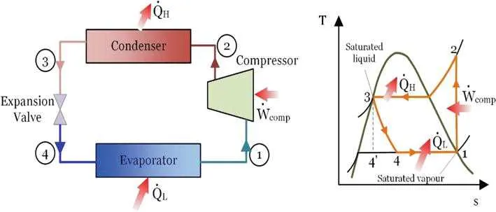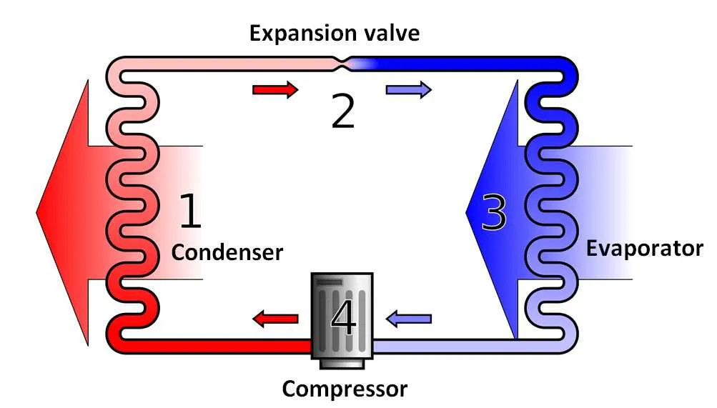
For optimal efficiency in a refrigeration or climate control setup, analyze the schematic representation of the thermodynamic process. This illustration reveals critical phases including compression, condensation, expansion, and evaporation, each impacting overall performance.
Compression increases the refrigerant’s pressure and temperature, preparing it for effective energy release during the subsequent stage. Monitoring pressure ratios here is essential to avoid mechanical strain and maximize output.
The condensation phase involves heat rejection to the surroundings, typically via a coil or radiator, transforming the gas into a liquid state. Ensuring proper heat exchange surfaces and fluid flow rates prevents efficiency losses.
Expansion valves or throttling devices reduce the pressure abruptly, allowing the fluid to cool significantly. Precise control of this step maintains system stability and prevents issues like icing or pressure drops.
During evaporation, the liquid absorbs environmental energy, vaporizing to complete the loop. The selection of appropriate evaporator size and placement directly affects energy absorption capacity and system reliability.
Thermodynamic Process Schematic
To optimize energy transfer systems for climate control, analyze the process flow that includes four main components: evaporator, compressor, condenser, and expansion valve. The refrigerant absorbs low-temperature ambient energy at the evaporator, transforming from liquid to vapor at constant pressure.
Following this, the vapor is compressed, raising its pressure and temperature significantly. The high-pressure, high-temperature gas then releases its energy to a warmer environment in the condenser, condensing back to liquid form. Finally, the liquid passes through the expansion device, where pressure drops abruptly, cooling the fluid before re-entering the evaporator.
On the pressure-enthalpy plot, the process forms a loop with clearly defined states: low-pressure vapor at the evaporator outlet, high-pressure vapor post-compression, high-pressure liquid after condensation, and low-pressure liquid after expansion. Monitoring these points ensures proper system performance and efficiency.
For improved system design, pay attention to superheating and subcooling levels. Proper superheat ensures vapor phase at compressor inlet, avoiding liquid damage, while adequate subcooling maximizes energy extraction in the condenser.
Effective visualization of this thermodynamic loop aids troubleshooting and optimization by highlighting pressure and temperature differentials across components, ensuring reliable operation and energy efficiency.
Interpreting Pressure-Temperature Relationships in the Refrigeration Loop
To accurately analyze the pressure-temperature correlation in a refrigeration system, use refrigerant-specific charts or software to correlate saturation pressure and temperature points. Precise interpretation allows for detecting inefficiencies and diagnosing operational issues.
- Measure pressure at key locations: compressor outlet, condenser inlet/outlet, expansion valve inlet, and evaporator inlet.
- Record corresponding temperatures at these points, preferably using thermocouples or RTDs for accuracy.
- Compare measured pressures to saturation pressures at measured temperatures using refrigerant property tables.
Key observations include:
- If pressure readings significantly exceed saturation pressures at measured temperature, superheating or subcooling may be indicated.
- Pressure below saturation at temperature typically suggests vapor quality changes or presence of non-condensables.
- Consistent pressure-temperature pairs that match refrigerant saturation data confirm proper phase transitions.
Apply these principles to optimize system efficiency:
- Ensure the condenser pressure aligns with the saturation pressure for the condenser temperature; deviations signal fouling or airflow issues.
- Verify evaporator pressure matches expected saturation values for desired cooling temperatures; mismatches may indicate refrigerant charge problems.
- Use pressure-temperature trends over time to anticipate component wear or refrigerant leaks.
Identifying Key Components and Their Roles Within the Process Schematic
Focus first on locating the evaporator, compressor, condenser, and expansion valve, as these four parts define the system’s function. The evaporator absorbs low-temperature thermal energy from the surroundings, causing the refrigerant to vaporize. Next, the compressor raises the pressure and temperature of this vapor, enabling efficient energy transfer.
The condenser then rejects the absorbed energy at a higher temperature to the environment, condensing the refrigerant back into a liquid state. The expansion valve controls the refrigerant flow, reducing pressure and temperature before it returns to the evaporator, completing the loop.
Each component is typically represented by distinct symbols: the compressor by a circle or a piston icon, the evaporator and condenser by coils or serpentine shapes, and the expansion device by a throttling valve symbol. Accurate identification ensures proper interpretation of energy transformation and fluid flow paths within the schematic.
Additional elements such as the accumulator, receiver, and reversing valve may appear in advanced layouts. The accumulator prevents liquid refrigerant from entering the compressor, protecting it from damage. The receiver stores excess refrigerant, while the reversing valve allows switching between cooling and heating modes in reversible systems.
Confirming component placement relative to pressure and temperature zones on the schematic assists in understanding operational sequences and diagnosing potential faults. Use labeled flow directions and temperature gradients to verify each part’s function within the system loop.
Troubleshooting Common Anomalies Using Cycle Chart Analysis

Identify pressure drops: If the condenser side pressure falls below expected values, inspect for refrigerant leaks or blockage in the external coil. Use pressure readings at key points on the thermodynamic path to pinpoint abnormal deviations.
Check evaporator superheat levels: Superheat values exceeding manufacturer specifications often indicate insufficient refrigerant flow or a malfunctioning expansion device. Measure temperature differences between inlet and outlet of the evaporator segment to verify this.
Detect compressor inefficiencies: Deviations in enthalpy before and after compression stages suggest mechanical wear or electrical faults. Compare actual power input and output states to design benchmarks to isolate performance loss.
Monitor subcooling irregularities: Lower-than-normal subcooling indicates potential issues with condenser effectiveness or overcharge. Track liquid line temperatures against saturation points to confirm fluid phase consistency.
Evaluate refrigerant charge: Both overcharging and undercharging manifest as shifts in pressure-enthalpy coordinates along the cycle path. Systematic plotting of these points helps determine optimal fluid quantity adjustments.
Routine state point analysis along the thermodynamic sequence reveals faults quickly, allowing targeted interventions such as cleaning coils, replacing valves, or adjusting controls to restore operational efficiency.