To ensure optimal performance of your recreational vehicle’s climate control unit, proper electrical installation is crucial. Focus on verifying the correct power source compatibility–typically 12V DC or 120V AC depending on the model–and ensure all grounding points are securely connected to avoid potential short circuits or malfunctions.
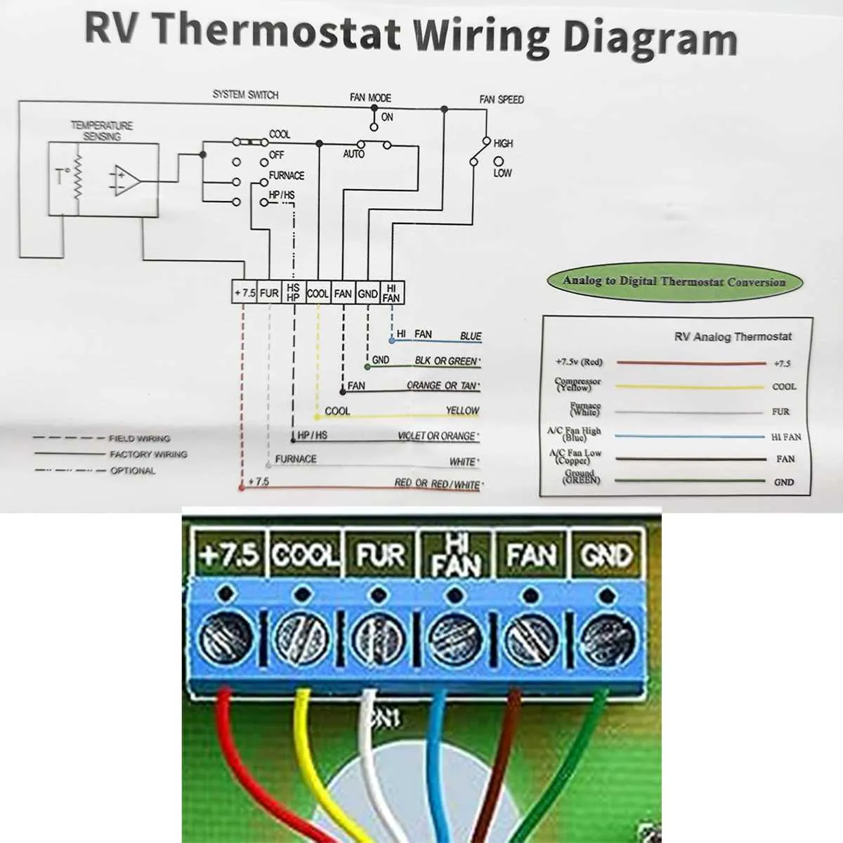
Use the manufacturer’s specific schematic to identify the precise terminals for compressor, fan motors, and thermostat wiring. Pay particular attention to the fuse ratings and relay configurations to prevent overloads and ensure system longevity.
When routing cables, maintain separation from high-current wiring to reduce electromagnetic interference. Always employ high-quality connectors and double-check polarity before energizing the setup. Proper labeling of wires during installation will simplify future troubleshooting and maintenance tasks.
RV Cooling Unit Electrical Connection Guide
For safe and efficient installation of the RV cooling system, follow this precise connection layout:
- Power Source: Use a dedicated 30-amp circuit breaker rated for 120V AC to supply electricity.
- Grounding: Ensure a solid grounding connection to the vehicle chassis to prevent electrical hazards.
- Thermostat Integration: Connect the thermostat control wires according to the manufacturer’s color coding–typically red for power, white for cooling signal, and yellow for fan operation.
- Compressor and Fan Wiring: Run separate leads from the main control board to the compressor motor and dual-speed fan motors, ensuring proper gauge wire (14 AWG minimum) to handle current load.
- Capacitor Connection: Include the start/run capacitor wiring as shown in the technical reference to optimize motor efficiency and longevity.
- Fuse Protection: Install inline fuses or circuit breakers on all power leads to protect against overload or short circuits.
- Control Board: Follow the pinout chart exactly when connecting the main circuit board to the components to avoid malfunction.
Use heat shrink tubing and wire connectors rated for outdoor or automotive use to secure all joints. Label each wire to simplify troubleshooting and maintenance. Avoid mixing neutral and hot wires to prevent system failure or electrical shock.
Identifying and Understanding Key Wiring Components

Start by locating the main power input terminals; these are typically marked as L (Line), N (Neutral), and G (Ground). Verify proper grounding to prevent electrical hazards and ensure system reliability. The control board is central to operation – identify its connector pins for thermostat signals, fan motor, compressor relay, and sensor inputs.
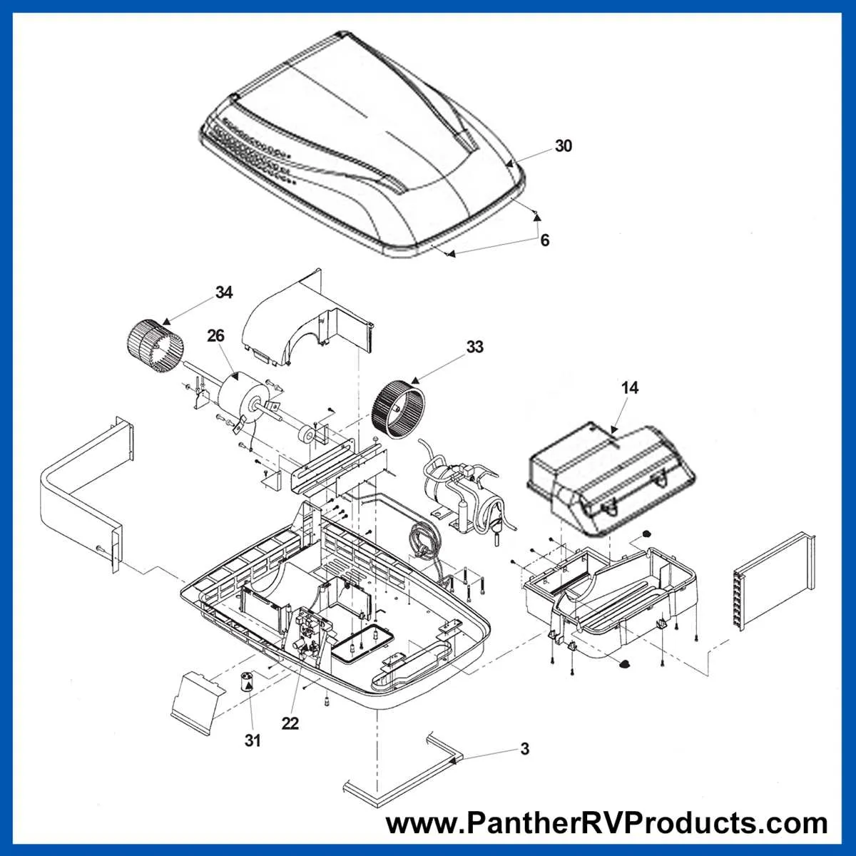
Look for the capacitor(s), usually cylindrical or oval-shaped, connected near the compressor or fan motors. These support motor startup and running efficiency. Recognize the transformer unit that steps down voltage for the control circuitry, often found near the control board.
Fuses and circuit breakers must be clearly identified; these protect against overload and short circuits. Note their ratings and positions relative to the power source. Thermostat wiring typically involves low-voltage leads; distinguish these by their thinner gauge and often color-coded insulation.
Trace fan motor leads–these usually consist of multiple wires for speed control or dual windings. Compressor connections include high-current cables and may be accompanied by overload protectors or relays. Sensors such as temperature probes or pressure switches connect to dedicated terminals on the control unit and require careful handling to avoid damage.
Always confirm wire gauge matches system requirements to avoid overheating. Document color codes and terminal labels as they vary by manufacturer but generally follow standard conventions. Utilize a multimeter to check continuity and proper voltage levels before final assembly.
Step-by-Step Guide to Connecting Power and Controls

Begin by ensuring the main power source is switched off before starting any electrical work. Identify the unit’s power input terminals, typically labeled as L (live), N (neutral), and G (ground). Use a multimeter to verify the absence of voltage.
Connect a properly rated circuit breaker or fuse to the power supply line to protect the system. Run a three-wire cable from the power source to the control panel, matching live, neutral, and ground wires accordingly. Secure all connections with insulated connectors to prevent short circuits.
Locate the control board terminals designed for thermostat input and fan speed controls. Connect the thermostat wiring according to the manufacturer’s pinout, often marked as R (power), W (cooling signal), and C (common). Use shielded cable if the wiring runs near high-power circuits to avoid interference.
Attach the remote control interface wiring to the corresponding terminals, following polarity guidelines strictly to avoid damage. For units with digital control modules, connect the communication cables, ensuring connectors are fully seated and locking clips engaged.
Double-check all connections for tightness and correct placement. Reinstall any protective covers or panels removed during installation. Restore power and test the system by cycling through all operational modes, monitoring for proper function and absence of unusual noises or errors.
If the unit includes a capacitor, confirm it is properly wired between the compressor and fan motor terminals as indicated in the service manual. Verify ground continuity with an ohmmeter to ensure safety compliance.
Troubleshooting Common Electrical Connection Issues in RV Cooling Units

Check all terminal connections for tightness and corrosion first. Loose or oxidized contacts often cause intermittent operation or complete failure. Use a multimeter to verify continuity and ensure no breaks in the cables supplying power.
Inspect the control board connectors for bent pins or damaged sockets. Faulty linkages here can disrupt signals between the thermostat and the compressor, leading to erratic cycling or no activation.
Verify proper voltage at the input terminals. The unit typically requires a steady 120V supply; any significant drop below 110V can impair performance. Use a voltage tester under load conditions to confirm stable power delivery.
Examine the ground connection carefully. An improper earth can cause safety hazards and erratic behavior. The chassis ground should be firmly attached to the RV’s metal frame with clean, paint-free contact points.
Check the capacitor wiring and condition. A failing start/run capacitor often shows visible swelling or leakage. Confirm correct wiring orientation according to the unit’s specifications; reversing leads may prevent compressor startup.
Replace any cracked or brittle insulation on cables to prevent shorts. Inspect junction boxes for moisture intrusion, which can corrode terminals and cause open circuits.
Ensure the thermostat sensor wiring is intact and correctly routed. Damaged or misconnected sensor wires can lead to incorrect temperature readings and faulty operation.
Test relays and fuses in the control circuit. A blown fuse or a stuck relay will interrupt power flow, halting unit function. Swap with known good components where possible to isolate the problem.