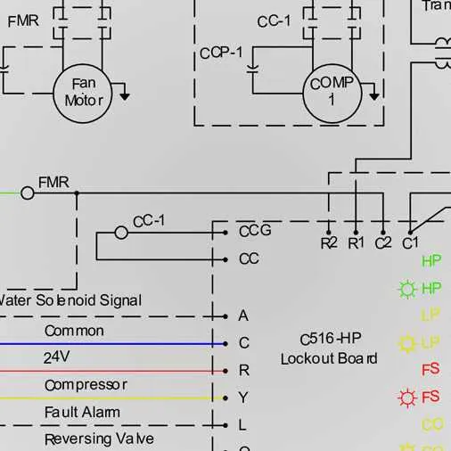
Start by identifying the main components: compressor, expansion valve, evaporator coil, and condenser coil. Accurately map their positions to optimize flow and minimize energy loss. Ensure that control devices such as thermostats and relays are integrated within close proximity to reduce signal interference and voltage drop.
Use standardized color codes for conductor identification–typically red for live, black for neutral, and green or bare copper for grounding. This prevents miswiring during installation or maintenance and enhances safety compliance.
Incorporate detailed layout plans highlighting connections between electrical terminals and mechanical parts. Double-check all relay coils, contactors, and overload protectors for correct voltage ratings matching your power source.
Label each connection point clearly with reference designators and wire gauge specifications to facilitate troubleshooting. Document fuse sizes and circuit breakers with their trip ratings to avoid overcurrent risks.
System Blueprints and Electrical Connections
Always refer to manufacturer-provided layouts to identify correct terminal assignments and voltage requirements. Typical configurations include single-phase or three-phase power inputs, with control circuits operating at 24V AC. Verify line voltage compatibility before installation to prevent component damage.
Key components such as compressors, reversing valves, and defrost controls must be connected following the specific pinout instructions. Use color-coded conductors to reduce wiring errors during service or replacement. Implement dedicated circuit breakers and disconnect switches per NEC standards.
For troubleshooting, trace control board pathways using the provided wiring maps, focusing on contactor coils and sensor inputs. Ensure ground connections are secure to avoid electrical noise that may cause erratic system behavior. Proper labeling of all cables enhances maintenance efficiency.
Integrate safety devices like pressure switches and thermal sensors with the main controller using specified input terminals. Confirm correct polarity and terminal torque values to maintain reliable electrical contact. Use schematic references to double-check relay coil wiring and auxiliary switches.
Interpreting Common Symbols and Components in HVAC Circuit Drawings
Start by identifying key icons representing major elements: compressors are often depicted as a circle with the letter “C” inside, while expansion devices appear as a narrow valve symbol. Recognize the fan by its distinct blade-like symbol, usually a circle with radial lines.
Focus on electrical components: relays are shown as rectangles with coil and contact designations, commonly labeled “RY” or “K.” Capacitors appear as parallel lines, and thermostats as switches with a temperature setpoint marking.
Trace refrigerant flow lines: solid lines indicate liquid pathways, dashed lines denote vapor routes. Pay attention to arrows that clarify direction, essential for understanding cycle logic.
Always cross-reference component tags with legend tables. Each label, such as “T1” for temperature sensors or “M” for motors, corresponds to specific parts. This eliminates ambiguity when reading complex layouts.
Electrical connections use standard line types: thick lines represent power feeds, thin lines control circuits. Junction points appear as dots where lines intersect; absence of a dot means no electrical connection.
Ground symbols are crucial for safety interpretation: typically three descending horizontal lines or a triangle shape. Confirm these to ensure correct earthing.
Recognizing these symbols and conventions accelerates troubleshooting and facilitates accurate interpretation of the system’s operation in technical drawings.
Step-by-Step Guide to Connecting a Climate Control Board
Begin by disconnecting all power sources to ensure safety before handling electrical components. Identify the terminals on the control board, typically labeled as R (24V power), C (common), Y (compressor contactor), G (fan relay), O/B (reversing valve), and W (auxiliary heat relay).
Attach the red wire to the R terminal to supply 24 volts AC. Connect the C terminal to the common wire from the transformer to complete the control circuit. Ensure the yellow wire links to the Y terminal to control the compressor function, allowing system activation.
Connect the green wire to the G terminal to enable the blower fan operation. If your model includes a reversing valve, connect the orange or blue wire to the O/B terminal, matching the system’s specifications. The white wire should be attached to the W terminal for emergency or auxiliary heating control.
Verify each connection is secure using a screwdriver and inspect for any loose strands that may cause shorts. Use a multimeter to test continuity and confirm voltage at appropriate terminals before restoring power. Avoid crossing wires or using damaged insulation to prevent malfunction or hazards.
Finally, after completing all terminals, restore power and perform a system test by cycling through modes to confirm the board properly directs each function. Monitor the response of the blower, compressor contactor, and reversing valve to ensure correct sequencing.
Troubleshooting Electrical Issues Using HVAC Circuit Layouts
Start by verifying power supply integrity at the main disconnect and control board terminals. Use a multimeter to confirm voltage presence and continuity through each control relay and contactor coil.
- Check fuses and circuit breakers for faults or trips before inspecting components.
- Identify control signals on thermostat wiring to ensure proper command transmission.
- Trace signal paths from transformer secondary outputs to safety switches and sensors to confirm uninterrupted current flow.
Use the control board layout to locate terminals for defrost controls, reversing valves, and fan motors. Test each coil resistance and signal voltage according to manufacturer specifications:
- Measure resistance values on motor windings and compare them to expected ranges (typically 1-10 ohms).
- Confirm relay activation by checking for voltage drop across contacts when energized.
- Inspect sensor inputs (temperature, pressure) by measuring their output voltage or resistance at connection points.
For intermittent operation, examine connectors and terminal blocks for corrosion or loose fittings. Tighten or replace as needed to restore reliable conductivity.
- Always isolate power before disconnecting or reconnecting components.
- Document test results for each circuit segment to streamline further diagnostics.