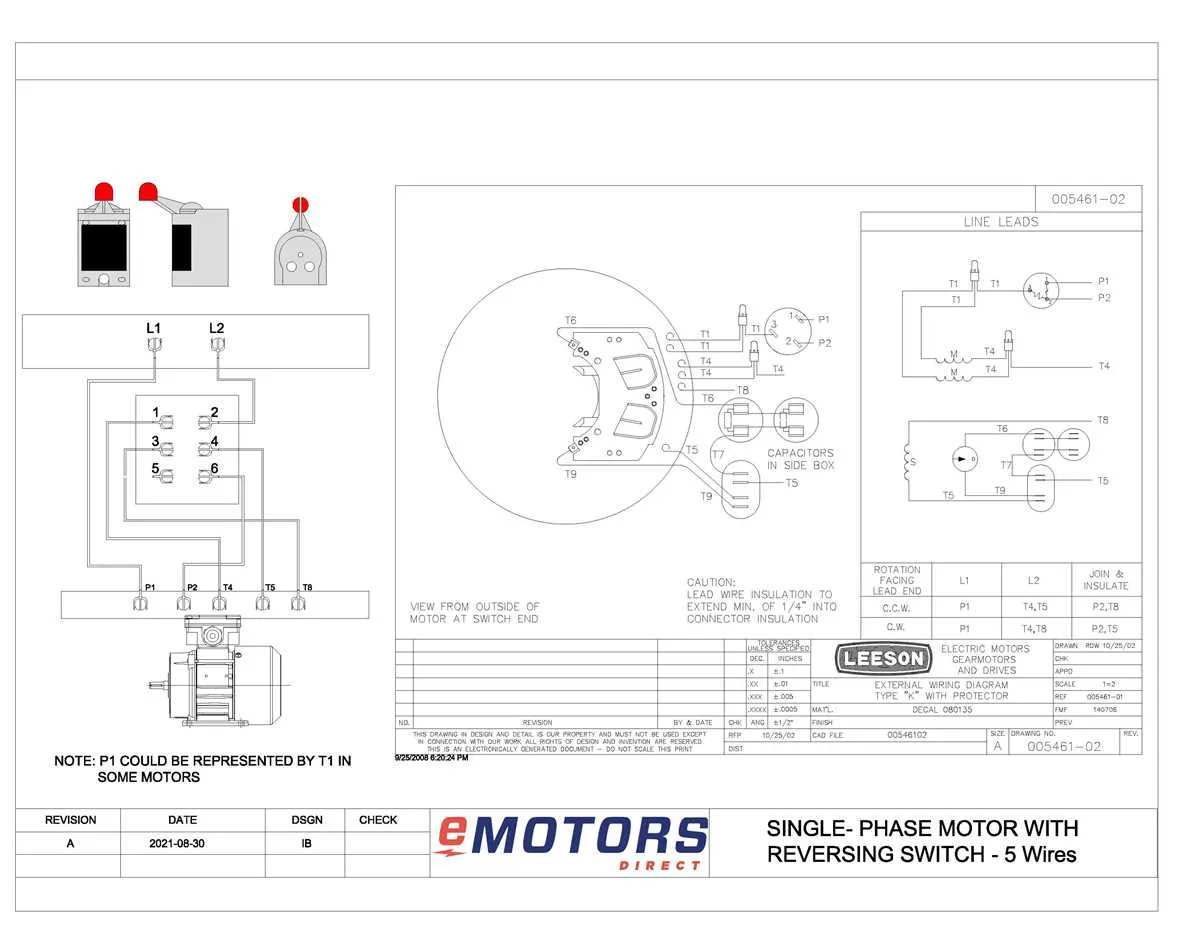
To ensure proper operation of your industrial equipment, follow a structured approach when connecting components. The key to success lies in accurate identification of terminals and following the exact sequence for each phase of the setup. Incorrect wiring can lead to equipment malfunction or even permanent damage, which can be costly.
Begin with a clear schematic that outlines each part of the connection process. Each section should clearly define the points of entry and exit for power, ensuring proper flow. Pay special attention to the voltage ratings and phase alignment to avoid errors. A reliable map of connections can significantly reduce troubleshooting time.
Double-check each component before starting the power-up procedure. Identify the starting and stopping components of your setup and verify that their positions are correctly indicated in the electrical instructions. Misplaced wires can create dangerous short circuits, which may lead to hazardous situations in your workspace.
Understanding Electrical Connections for Leeson Motors
Ensure accurate setup by identifying the terminal points on the power unit. Begin by connecting the power supply leads to the designated input terminals, typically marked L1, L2, and L3 for three-phase systems, or L and N for single-phase configurations.
For a single-phase setup, the capacitor is often placed in series with one of the leads, ensuring proper phase shift. Verify the proper orientation of the capacitor, as incorrect wiring may cause malfunction or reduced performance.
In three-phase systems, the phases must be correctly aligned to avoid reverse rotation. Double-check the sequence of phases and verify the direction of rotation before powering up the equipment. If necessary, adjust the connections to switch the direction of the shaft.
Grounding is critical for safety. Always connect the grounding wire to the designated terminal. This prevents electrical shocks and ensures compliance with safety standards.
If your setup includes a thermal overload relay, connect it in series with the power input lines. This will protect the unit from damage due to excessive current, automatically shutting off power when the set limits are exceeded.
Finally, check for any loose connections and confirm that all terminals are securely tightened. Any poor connections could lead to overheating or malfunction.
How to Interpret Leeson Motor Wiring Schematic for Single-Phase Motors
To correctly understand the schematic for a single-phase unit, follow these key steps:
- Identify the power supply terminals: Locate the line (L) and neutral (N) terminals. These connect the power source to the system.
- Understand the connection of the start and run windings: Check which windings are involved in starting and running the device. Start winding is typically used only during startup, while the run winding stays engaged throughout operation.
- Look for capacitors: If present, capacitors are connected to either the start winding or the main winding to improve performance. Identify their ratings and ensure proper placement.
- Verify the switch type: Confirm whether the schematic uses a centrifugal switch or another type to disconnect the start winding once the unit reaches running speed.
- Trace the connections: Carefully follow the path from the supply terminals to the windings. Ensure all components are connected properly, checking for any possible short circuits or open connections.
- Inspect the control circuit: In some setups, a thermal overload relay or a capacitor may be part of the circuit. Identify these elements and their connections to ensure the unit operates safely.
Follow these steps to accurately interpret and connect the system, ensuring proper operation and longevity of the unit.
Step-by-Step Guide to Wiring Leeson Three-Phase Motors

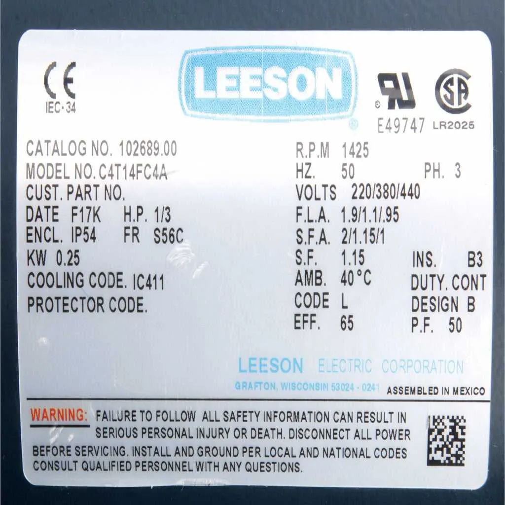
Start by identifying the power supply and ensuring the voltage matches the requirements of the device. Check the nameplate for correct voltage and current specifications. Ensure the circuit breaker is appropriately rated for the application.
Secure the connections for the three-phase supply. Connect each phase wire (L1, L2, and L3) to the corresponding terminals on the device, ensuring proper alignment with the motor’s designated terminals. The ground wire should be attached to the motor frame for safety.
Locate the terminal block for the starting method. If using a star-delta starter, connect the motor’s windings to the terminal block in a specific configuration that allows efficient switching from star to delta once up to speed. Use the wiring guidelines from the starter manufacturer for specific terminal placement.
After securing the connections, ensure that all terminals are tightened properly to prevent overheating or loose connections. Test the continuity with a multimeter to verify that there are no shorts between phases.
Before switching on the power, check that all safety switches are operational and that the installation follows the proper grounding standards to prevent electrical shock hazards. Once everything is verified, power on the unit and observe its operation for any unusual sounds or vibrations.
If necessary, adjust the settings on the starter or drive control panel to meet the desired performance parameters.
Troubleshooting Common Electrical Issues in Motors

Start by checking for power supply interruptions. A lack of voltage is a frequent cause of malfunction. Use a multimeter to confirm that the terminals are receiving the correct current. If there’s no power, inspect the circuit breaker or fuse and replace if necessary.
Next, examine the connections. Loose or corroded terminals can lead to poor performance or complete failure. Tighten all connections and clean any corrosion using a wire brush or contact cleaner. Replacing old or damaged terminals might be necessary.
If the unit is not starting, the problem might lie in the control switch or capacitor. Test the switch for continuity using a multimeter. For the capacitor, look for visible signs of damage such as bulging or leaking. A faulty capacitor should be replaced immediately.
Incorrect polarity can also cause malfunction. Verify that the incoming lines are correctly connected according to the manufacturer’s guidelines. If they are reversed, swap the connections, ensuring correct phase alignment.
Overheating is often caused by faulty connections or excessive current draw. Check for short circuits or improperly sized wires that may cause excess heat. Ensure that the conductors meet the specifications for the device’s requirements.
Finally, inspect the grounding. A poor ground connection can create electrical feedback, causing erratic behavior. Make sure the grounding wire is intact and securely attached to both the housing and the ground point.