Begin by consulting the exploded schematic to pinpoint the oil delivery unit at reference 3–regular lubrication here extends engine life by up to 25% and prevents premature wear.
Locate the centrifugal clutch assembly at position 9 and verify clearances of 0.2–0.4 mm; tightening the spring tension by one notch enhances engagement stability under heavy load.
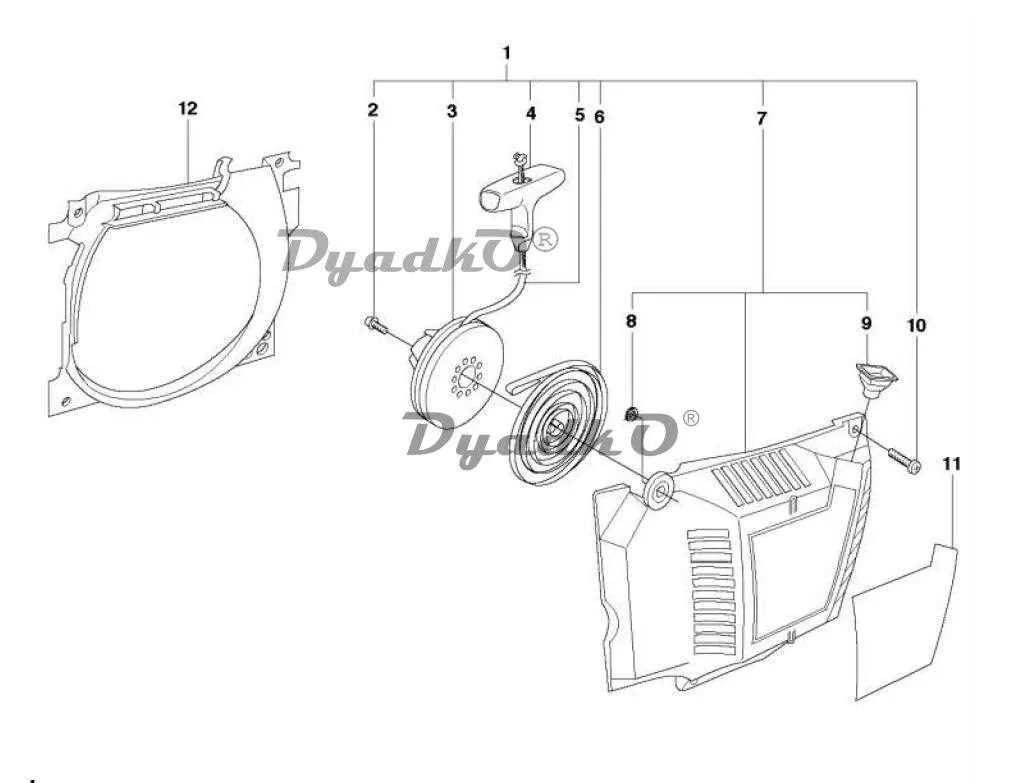
Inspect the recoil starter housing around index 12: confirm the rewind spring tension at 1.7 Nm and replace any frayed starter cord to avoid sudden pull resistance.
Check the ignition coil and spark plug interface at point 15–ensure a gap of 0.5 mm for optimal spark timing; use 20 kΩ/cm insulation testers to detect hidden shorts in the high-tension lead.
Precision Layout for Your 59cc Professional-Grade Cutter

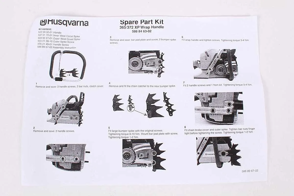
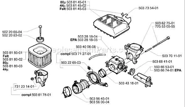
Consult the exploded-view schematic before sourcing replacements to ensure each element aligns with the factory reference numbers.
- Cylinder Assembly: Confirm gasket thickness and piston ring orientation per index code.
- Crankcase Housing: Inspect bearing seats for wear; replace seals using OEM cross-reference numbers.
- Ignition Module: Match coil gap to 0.4 mm and verify magneto timing via service manual spec.
- Fuel System Cluster: Clean jet orifices; renew diaphragm and needle valve using kit #544 XXX XXX.
- Bar & Chain Interface: Align sprocket teeth count (7 or 9) with chain gauge (0.325″ or 3/8″); torque axle nut to 30 Nm.
- Starter Mechanism: Replace recoil spring if pull tension exceeds 15 N; use guide pin #574 XXX XXX for proper alignment.
- Handle Units: Tighten anti-vibration mounts to 5 Nm; inspect rubber dampers for cracks and hardening.
- Air Filter Housing: Use foam pre-filter and paper element specified in service bulletin; secure cover clips to prevent leaks.
- Cross-check reference codes on the schematic with numbered tags on your saw before ordering.
- Group similar components (fasteners, gaskets, seals) to streamline rebuild kits.
- Use torque settings and part numbers directly from the service brochure to avoid misfits.
Locating Specific Components in the Engine Assembly
Begin inspection at the cylinder head’s front mounting flange to identify the ignition module: it sits directly above the fuel mixture intake port and is secured by two M5 bolts. Verify the 0.3 mm air gap between the sensor coil and flywheel magnets before removal to ensure proper spark timing.
Trace the primary drive shaft upward to locate the centrifugal clutch drum: it engages roughly 30 mm behind the crankcase face. Examine the star-pattern wear on the inner hub; excessive scoring indicates premature engagement and warrants replacement.
Access the fuel pump diaphragm beneath the left crankcase cover by removing three T27 screws. Mark the gasket orientation for accurate resealing, then test the inlet valve spring tension with a 12 N ±1 N gauge to confirm correct fuel delivery pressure.
Find the oil pump drive gear next to the rear crankshaft bearing within the lower housing. It meshes into a 20-tooth recess–inspect each tooth for chips and measure side clearance at 0.05 mm to prevent lubrication blockages.
Locate the recoil starter assembly by following the pull-cord housing: note the alignment tab at the 2 o’clock position relative to the serial number plate. This ensures the cover is refitted without misalignment that could affect starter engagement.
Understanding the Clutch and Oil Pump Configuration

Position the drive assembly so friction shoes seat evenly around the drum; tighten anchor bolt to 15 Nm and confirm 0.20 – 0.30 mm radial clearance between drum face and housing flange. Inspect shoe springs for 16 N preload and replace if tension drops below 12 N. Grease inner bearing race lightly with high-temperature grease to prevent slippage under load.
Set the lubrication pump plunger clearance at 0.25 mm, measured between plunger tip and cover plate. Verify flow rate of 200 ml/min at 3 000 rpm; adjust eccentric cam position by rotating housing 10° counter-clockwise if flow falls below 180 ml/min. Change oil pump seal annually or after 100 hours of operation to maintain consistent pressure.
| Component | Tolerance / Rate | Service Action |
|---|---|---|
| Friction shoes | Preload 16 ± 2 N | Replace if |
| Drum clearance | 0.20 – 0.30 mm | Adjust or shim housing flange |
| Pump plunger gap | 0.25 mm | Recheck after cover plate removal |
| Oil flow | 200 ml/min @ 3 000 rpm | Realign cam if |
| Seal rings | Nitrile, 6.0 × 1.8 mm | Replace yearly or 100 h |
How to Identify Replacement Part Numbers from the Diagram

Start by locating the exact section of the schematic that corresponds to the malfunctioning component, such as the ignition system or clutch assembly. Each element in the illustration is labeled with a unique reference code.
Cross-reference this code with the numerical index typically listed adjacent to the graphic. These indices point to a detailed legend or table that assigns official identification numbers to every component.
Verify compatibility by checking the serial range noted near the index–some assemblies vary slightly across production years. Always select the number that aligns with your unit’s manufacturing series.
To avoid confusion, ignore duplicated visuals showing sub-assemblies; rely only on the item index that matches the main exploded view. When multiple variants are listed, choose based on features like bar length or cylinder displacement noted in the table.
Use searchable part ID numbers, not descriptive names, when ordering or searching online to ensure accurate replacement.