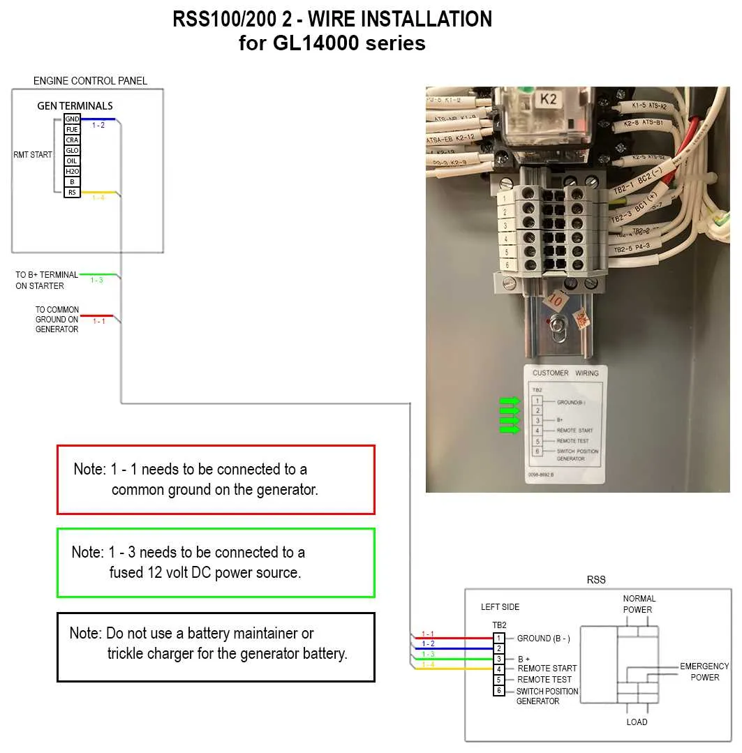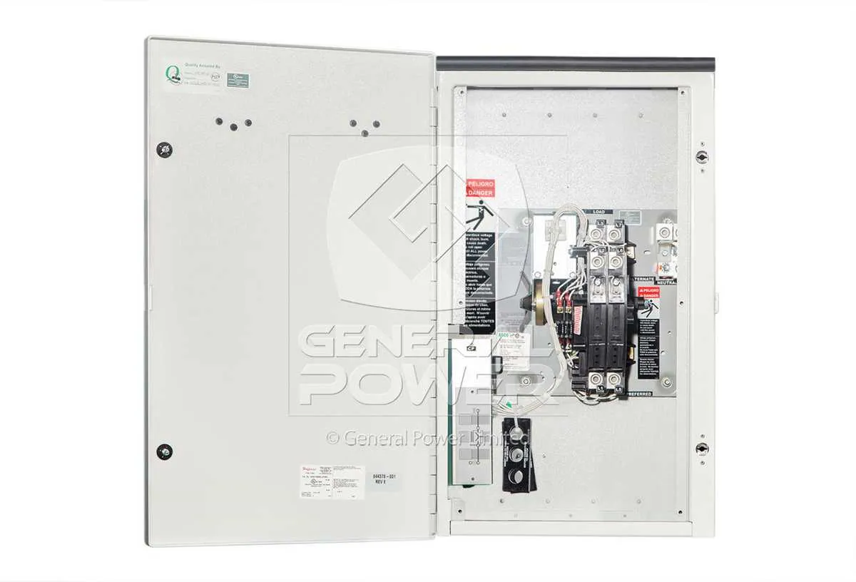
For proper installation of a 200-Amp power circuit control system, follow these steps for a safe and reliable connection. First, ensure you have the appropriate components, including a high-capacity electrical panel, reliable circuit breakers, and quality cabling for optimal performance. It’s essential to understand how each part integrates into the overall system to prevent future issues.
Start by connecting the main power input to the distribution panel, ensuring you meet the load requirements and the total current capacity. Verify the correct gauge of cables for both incoming and outgoing circuits to avoid overheating and potential failures. Each wire should be connected securely to prevent loose connections that could lead to arcing.
Next, focus on the power control relay, which is crucial for managing electrical flow. This relay should be mounted according to manufacturer guidelines, ensuring it’s within reach for maintenance but still protected from potential environmental hazards. A correctly installed relay will prevent overloads and maintain the system’s functionality under varying power demands.
Finally, check all connections and ensure that grounding is done properly. Grounding ensures the safety of the entire installation by diverting any stray electrical current to the earth, avoiding electrical shock hazards. Regularly inspect connections for corrosion or wear to maintain system integrity over time.
Electrical Control Panel Setup for 240V Power Backup
To successfully integrate a backup power system, follow these precise guidelines for connecting the primary and secondary power sources. This method ensures seamless operation when switching between grid and generator power.
- Power Source Connections: Connect the utility power and generator lines to their respective terminals. Ensure each is securely fastened to avoid loose connections which can lead to power interruptions.
- Neutral Connections: The neutral line from both the grid and generator should be properly isolated. Never connect both neutrals together unless the system is designed for it, as this can create hazardous conditions.
- Grounding: Grounding the unit is essential for safety. Use an appropriate ground rod and ensure all metal components are properly earthed to prevent electrocution or equipment damage.
- Transfer Mechanism: Install the transfer mechanism in a manner that allows it to automatically shift between the utility and backup power. Ensure the contactor’s voltage ratings match the requirements of both sources.
- Load Breaker Configuration: Breaker ratings should match the expected load requirements. Ensure that the load breakers are correctly assigned to specific circuits, and all connections are made to handle the required load safely.
- Test the Setup: After installation, run thorough tests to confirm the backup system activates when utility power is lost. Check both the voltage and current on all relevant circuits to ensure safe operation.
For installation involving high-powered equipment, consult with an electrical expert to verify that all connections meet local electrical codes and safety standards.
How to Connect a 200-Amp Backup Power System for Home Use

To safely connect a backup power system for your home, begin by shutting off the main breaker to ensure no current flows while you work. Next, identify the input terminals from the power source (utility grid) and the output terminals that connect to your backup generator or power source. The input terminals must be connected to the utility line, while the output terminals will direct power to the home’s electrical panel.
Ensure you use appropriately rated cables for the load. Typically, #4 copper or #2 aluminum wires are required for high-load applications. Attach the utility input leads to the designated terminals, ensuring they are tightly secured. Likewise, connect the generator leads to the appropriate output terminals, securing them with the same level of attention to safety and stability.
Neutral wiring is essential. Ensure the neutral wire from the generator is linked to the neutral bus bar in your home’s panel, and connect the generator’s ground wire to the system ground. Any loose connections could result in serious issues, including fire hazards or equipment damage.
Once all connections are made, double-check for proper grounding to prevent electrical shock risks. After confirming all terminals are secure, test the system to verify its functionality. Run the generator and check that it successfully powers the household systems without any irregularities in voltage or power flow.
Always adhere to local electrical codes and, when in doubt, consult a licensed electrician. Proper installation and periodic maintenance are critical for safe and reliable operation.
Common Electrical Connection Mistakes to Avoid
Ensure that all connections are tightly secured, as loose terminals can lead to overheating and potential failure. Check each terminal after installation for proper torque to prevent arcing.
Don’t skip grounding. A properly grounded system protects against electrical shocks and equipment damage. Always verify the grounding system according to local regulations to avoid serious safety hazards.
Incorrectly sized conductors are a common issue. Ensure that the wire gauge matches the expected load. Undersized cables can overheat and cause a fire hazard. Consult the manufacturer’s specifications for correct wire size and ratings.
Be cautious with neutral connections. Inaccurate neutral to ground wiring can cause imbalances, leading to potential shock risks or equipment damage. Ensure that the neutral and ground are not bonded unless explicitly required by the installation instructions.
Avoid overloading circuits by not exceeding the specified maximum current for any connected loads. Always calculate the total current consumption to ensure that the system can handle the load without risk of overheating or failure.
Check for proper placement of the system to ensure air circulation and cooling. Installing in confined or obstructed areas can increase the risk of overheating and reduce the lifespan of the equipment.
Use correct cable entry points and sealing methods. Improperly sealed holes can let moisture in, which may corrode connections or short-circuit the system. Always use proper sealing techniques for waterproof and dustproof performance.
Finally, double-check the phase alignment if multiple circuits are involved. Incorrect phase sequencing can lead to operational failure and equipment damage. Make sure each phase is correctly connected as per the manufacturer’s guidelines.
Step-by-Step Guide for Connecting Generator and Utility Power to an ATS
1. Preparation: Before starting, ensure that the power supply is completely turned off from both the utility grid and the generator. Verify that the ATS is compatible with the electrical load and installation requirements. Gather all necessary tools, connectors, and safety gear.
2. Mounting the ATS: Securely mount the ATS in a dry, accessible location near the main service panel and the generator. Ensure the device is placed according to manufacturer recommendations for optimal performance and safety.
3. Connecting the Utility Input: Begin by connecting the utility power source to the designated terminals on the ATS. Use appropriate gauge wire that matches the expected load and local electrical codes. Tighten connections to avoid loose wiring that could cause overheating or faults.
4. Generator Input Setup: Similarly, connect the generator’s output terminals to the corresponding input connections on the ATS. Use wires that can handle the generator’s power output, ensuring a secure and solid connection. Ensure the generator is capable of automatic startup once the utility power goes down.
5. Grounding: Ground the ATS according to local electrical code requirements. This is critical for preventing electrical shock or damage to connected devices. Use a grounding rod or the grounding system of your main service panel.
6. Neutral-to-Ground Bonding: In some installations, it may be necessary to bond the neutral conductor to the ground at the ATS. Verify the specific requirements from the manufacturer or consult a licensed electrician.
7. Testing and Commissioning: After all connections are made, perform a system test. Simulate a power outage by turning off the utility power supply and ensure the ATS switches seamlessly to the generator power. Verify that the transfer mechanism functions without delay and check for any faults in the system.
8. Final Inspection: Inspect all connections for tightness, correct installation, and proper grounding. Verify that all wiring follows local codes and that the system is safe for operation. If unsure, hire a licensed electrician for a final check.