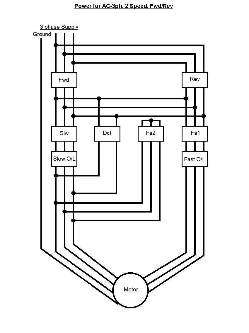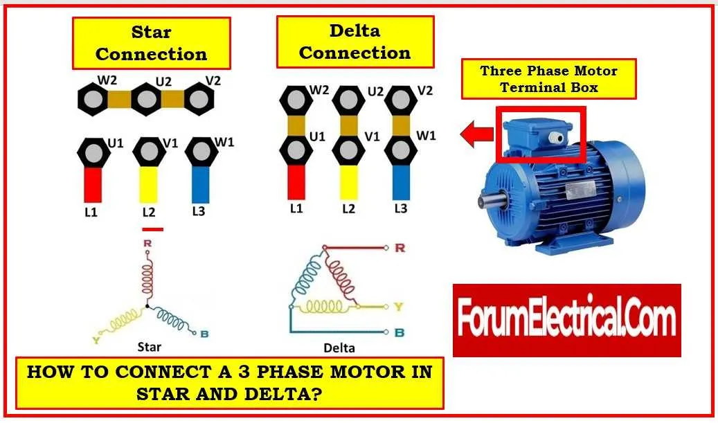
To properly connect a 3-phase electric machine, it’s essential to follow a systematic process. The correct approach ensures efficiency and prevents any potential damage to the equipment. First, identify the type of connection required–whether it’s a star or delta configuration. Each offers distinct advantages based on the voltage and load characteristics of the system.
Star connection is ideal when lower voltage is needed at the terminals, reducing the current demand. This configuration provides a balance between power distribution and ease of control, making it suitable for situations with higher voltage requirements. On the other hand, the delta configuration is better when a higher starting torque is required, delivering more power at the cost of increased current draw.
Ensure that the correct wire gauge is selected for both the load and the supply voltage. A larger gauge will reduce power losses, but it comes at a higher initial cost. Additionally, insulation ratings should match the expected temperature range of the machine’s environment to prevent premature failure. Never neglect the grounding system, as it plays a crucial role in ensuring safety and preventing electrical hazards.
Lastly, always verify connections and phases before energizing the system. Improper wiring can result in unbalanced loads, leading to operational inefficiency or, worse, equipment damage. Regular maintenance checks should be scheduled to confirm that all components are functioning within their specified parameters.
Connection Guide for 3-Phase Electric Machines

To ensure optimal performance and safety when setting up a 3-phase electric machine, follow these specific steps. The most common method is a star (Y) or delta (Δ) setup, depending on your voltage requirements.
Step 1: Identify the terminal block with the three input lines labeled L1, L2, and L3. These correspond to the three conductors supplying alternating current from the electrical network.
Step 2: Choose the appropriate configuration–star or delta–depending on whether you need lower current for a higher voltage or vice versa. For a star connection, connect one end of each coil to a central point (neutral), while the other ends are connected to the lines. In delta, the three ends of the coils form a closed loop, each connected to a line.
Step 3: Ensure the neutral point is grounded to avoid electrical hazards. The earth connection is crucial for safety, protecting against leakage currents.
Step 4: If a protective relay or circuit breaker is used, wire it between the input and the machine, with proper overload and short-circuit protection values set based on the machine’s power rating.
Step 5: Test the machine by measuring the voltage across each coil to ensure balanced input. If the voltage readings are uneven, troubleshoot for issues like incorrect connections or faulty components.
Step 6: Always verify that all connections are secure and insulated. Any loose or exposed wires can lead to dangerous electrical faults.
Note: If unsure about the setup, consult the manufacturer’s manual for specific connection instructions tailored to your equipment. Incorrect configurations can lead to overheating or malfunction.
Understanding the Basic Components in a 3 Phase Motor Circuit
When setting up an electrical connection for a 3-phase motor, it’s essential to comprehend the basic elements involved in the system. Each component plays a specific role in ensuring proper operation and safety. Below is a breakdown of the key parts commonly found in such setups:
- Power Supply: A 3-phase power source provides three alternating currents with a 120-degree offset, delivering a continuous and efficient flow of energy to the connected load.
- Contactor: This electrically controlled switch facilitates or interrupts the flow of electricity, ensuring that the motor can be safely turned on and off. It’s critical for protecting circuits against overloads.
- Overload Protection: These devices detect excessive current and prevent damage by cutting off power. Typically, they are integrated into the contactor system or placed separately as an additional layer of safety.
- Starter: The starter regulates the initial current sent to the load. Depending on the motor’s requirements, it can be direct-on-line, star-delta, or soft start, all of which help to minimize the starting current.
- Switches: Manual or automatic switches are used to isolate the motor from the power supply. These can be lever-type or push-button switches, depending on the control system design.
- Capacitor (if applicable): In certain systems, capacitors are used to improve power factor, especially in smaller motors or applications with variable loads. They help reduce the lag between the voltage and current, improving efficiency.
- Connection Terminals: These are the points where power leads from the supply are attached to the motor. Proper insulation and secure connections are crucial to prevent short circuits or electrical hazards.
- Control Circuit: This includes all auxiliary components, such as relays and switches, that control the sequence of operations, ensuring the motor runs according to the desired logic (e.g., forward or reverse rotation).
Each element has a precise function, and proper selection and integration of these parts ensure the motor runs efficiently, safely, and within its operational limits. Always verify that the components are rated for the specific motor’s requirements to avoid system failures.
How to Connect a 3-Phase Induction Unit with a Contactor and Overload Protection
Start by selecting a contactor rated for the current draw of the induction unit. The contactor must have a coil voltage matching the control circuit (often 110V, 220V, or 380V). For overload protection, use a thermal overload relay with a current rating matching the motor’s full-load amperage (FLA). Ensure proper coordination between the relay and the contactor for accurate protection.
Connect the three incoming supply lines (L1, L2, L3) to the contactor’s main terminals. The outgoing lines from the contactor connect to the three terminals of the induction unit. The neutral line is typically not required for a three-phase unit unless specified by the manufacturer.
Wire the control circuit. For start/stop control, incorporate a start button (normally open) and a stop button (normally closed). These should be wired in series with the contactor coil, ensuring safe operation. When the start button is pressed, it energizes the contactor coil, closing the contacts and supplying current to the machine.
Place the overload relay in series with the line connection to the machine, ensuring it is positioned between the contactor and the unit. Set the relay to trip at the unit’s rated current to protect against overheating or overcurrent conditions.
Test the setup by running the unit briefly, checking for proper operation of the contactor and overload relay. If everything functions correctly, finalize the wiring and secure all connections. Ensure that all wiring is insulated and rated for the current levels expected in the circuit.
Common Mistakes to Avoid When Installing a 3-Phase Electric Machine
Ensure proper identification of the leads before connecting them to prevent incorrect phasing. Interchanging any two wires can cause the equipment to rotate in the wrong direction, leading to operational inefficiencies or damage.
Verify that the supply voltage matches the specifications of the system. A mismatch can cause overheating, reduced efficiency, or failure of key components. Always double-check voltage ratings from the manufacturer’s datasheet.
Neglecting to properly ground the setup can lead to electrical hazards, including shocks or short circuits. A solid grounding system is essential to ensure safety and the longevity of the equipment.
Do not bypass overload protection circuits. These safety features are critical for preventing the system from running under excessive load, which could burn out the components. Always test these protection circuits before starting the operation.
Failure to check wire gauge size can lead to overheating and potential system failure. Ensure the wire thickness is sufficient to carry the full load without excessive voltage drop.
Using improper connection techniques, such as loose or poorly secured terminal blocks, can create electrical arcing or unreliable operation. Use the correct torque settings and secure terminals tightly to ensure stable current flow.
Incorrectly configuring the rotation direction of the machine can cause mechanical damage or inefficiency. Verify rotation before fully engaging the system by momentarily powering it on to check the spin direction.
Overlooking proper phase balancing across all conductors can result in uneven load distribution, leading to equipment stress and reduced operational life. Check that the current draw is consistent across all phases.
Do not neglect proper insulation of wires. Exposed or damaged cables can lead to short circuits or electrical hazards. Ensure all conductors are fully insulated and routed properly to avoid contact with any surfaces that could damage the insulation.