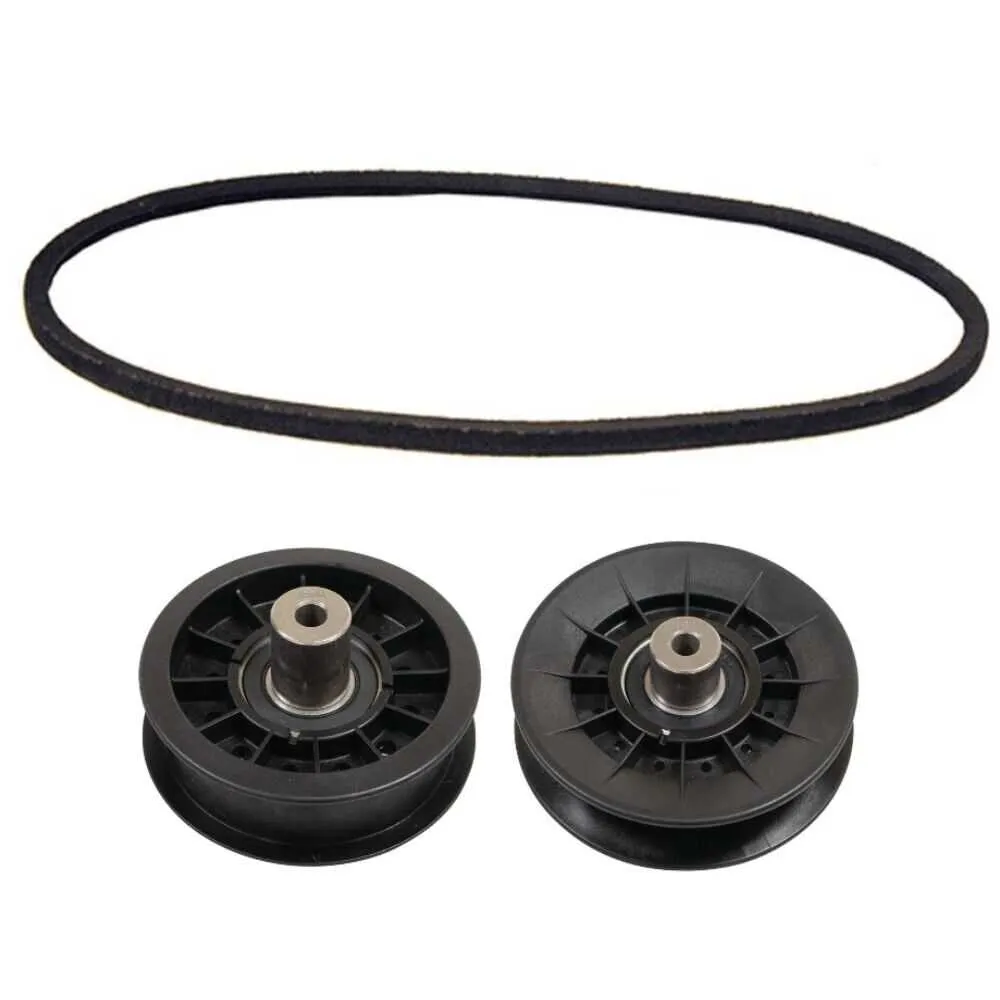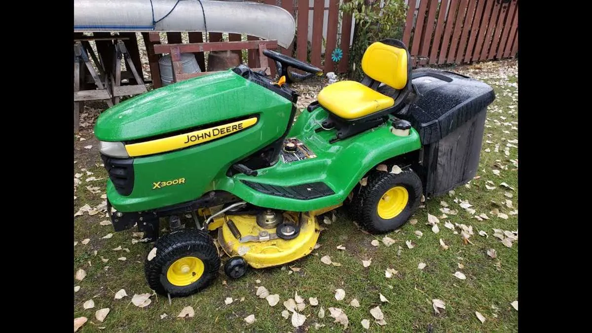
For optimal maintenance of the X300 lawn tractor, precise knowledge of the engine pulley system is essential. The arrangement of the power transfer loop significantly impacts the machine’s performance and longevity. Always verify the exact routing pattern before replacing the strap to ensure smooth operation and avoid premature wear.
Key points to check: tensioner position, correct pulley alignment, and the direction of the looping path around each component. Misalignment or incorrect placement can lead to slipping or damage, reducing efficiency and increasing repair costs.
Referencing a detailed schematic of the transmission loop helps identify the exact points of contact and threading, allowing for accurate reinstallation. This also facilitates troubleshooting issues related to slipping, squeaking, or loss of power transfer, common in older or heavily used units.
Drive Pulley and Tensioner Layout for the X300 Series
For proper routing of the primary power transmission strap on this lawn tractor model, follow the sequence below to ensure optimal performance and prevent premature wear.
- Start at the crankshaft pulley located at the engine base.
- Guide the loop upward around the idler pulley that controls tension.
- Route it around the spindle pulleys attached to the cutting deck.
- Pass the strap under the deck’s frame brackets to maintain alignment.
- Ensure the belt crosses over the tensioner arm before returning to the crankshaft pulley.
Check the strap for correct positioning on all pulleys to avoid slipping or noise. Replace if cracks or fraying are present.
- Inspect tensioner spring for adequate pressure.
- Clean pulleys from debris or grease buildup.
- Verify alignment of pulleys to prevent uneven wear.
- Adjust tensioner arm if the strap is too loose or too tight.
Following this precise path keeps the transmission system running smoothly and prolongs component life.
Locating and Identifying Key Components of the Transmission Strap on the X300 Model
Start by removing the mower deck to access the main pulley system beneath the chassis. The primary strap runs from the engine pulley to the transmission pulley; both should be clearly visible once the cover is lifted. The tensioner pulley, usually spring-loaded, is positioned adjacent to the idler arm and maintains proper tension on the loop. Inspect the tensioner for smooth rotation and check for wear on the rubber surface.
Trace the routing path carefully: the strap first loops around the crankshaft pulley, then extends to the idler pulley, which guides it towards the hydrostatic transmission drum. Look for any signs of fraying or cracking, especially near tight bends. Identifying the smaller guide pulleys along the frame will help confirm the correct path and prevent misalignment during reassembly.
Use the service manual illustrations to match pulley shapes and placement, as some pulleys have distinct sizes or grooves designed for specific belt widths. The tightness can be adjusted via the idler arm bracket bolts; ensure these bolts are loosened before attempting any replacement or repositioning.
Step-by-Step Guide to Removing and Replacing the Transmission Pulley Strap

Begin by disconnecting the spark plug to prevent accidental engine start. Raise the mower deck and secure it for easy access. Locate the main pulley strap connecting the engine to the mower blades. Release the tension by loosening the idler pulley bolt or using the tensioner arm to create slack.
Slide the old pulley strap off the engine crankshaft pulley and the spindle pulleys. Inspect all pulleys for wear or damage before installing the new component. Position the replacement strap carefully around the crankshaft pulley first, then route it through the idler and spindle pulleys following the original path.
Apply tension by adjusting the idler pulley or tensioner arm until the strap sits firmly without excessive slack. Ensure the strap aligns properly with all pulley grooves to avoid slipping. Lower the mower deck back to its operating position and reconnect the spark plug.
Start the engine briefly to confirm the new strap moves smoothly and without noise. If any unusual sounds or vibrations appear, stop the engine immediately and check the installation. Routine checks every season will extend the life of these components and prevent unexpected breakdowns.
Troubleshooting Common Issues with the Primary Power Transmission Strap on the X300 Model
Inspect the main pulley for wear or debris causing slipping or unusual noise. Replace any cracked or frayed straps immediately to avoid further damage.
Check tension by pressing on the span of the belt; it should deflect about 1/2 inch under moderate pressure. Adjust the idler arm to restore proper tightness if slack is detected.
Look for misalignment between the pulleys, which often leads to premature deterioration. Realign components using the manufacturer’s adjustment points to ensure smooth operation.
Grease pivot points on tensioners to prevent sticking and irregular strap movement. Lubrication extends component lifespan and reduces strain.
Inspect for oil or coolant contamination on the strap surface, which reduces grip and accelerates wear. Clean pulleys and replace the strap if contamination persists.
Evaluate the condition of related hardware such as tension springs and pulleys. Replace worn or damaged parts to maintain proper power transmission.
Ensure that all mounting bolts are tight, as loose fittings cause vibration and uneven wear patterns. Use a torque wrench following factory specifications.