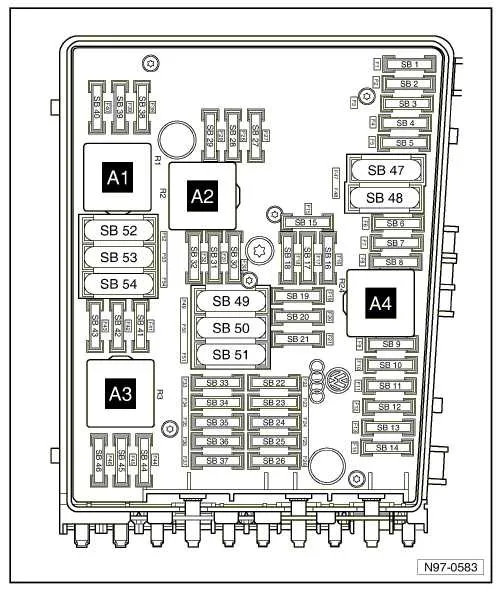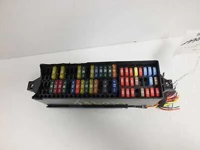
When troubleshooting electrical issues, knowing the exact layout of the car’s circuitry is essential for a smooth repair process. For owners of VW models from this era, the primary component to inspect is the central control unit, which manages various electrical functions. Identifying which part of the system is responsible for malfunctioning can save both time and money.
The location of the key components is well-documented, and understanding the exact placement of each unit can help pinpoint potential issues without unnecessary guesswork. Always begin by checking the main junction box under the dashboard and the auxiliary box near the engine compartment. These two areas are critical for most electrical operations, and being familiar with their configuration will allow you to address common problems like non-functioning lights, faulty climate control, or issues with the ignition system.
Ensure that each terminal and connector is intact, and always use the recommended amperage values when replacing any components. Properly matching components will prevent further damage and ensure long-lasting repairs. If you’re unsure of where to begin, a detailed map of the car’s power distribution system will guide you through the necessary steps for locating and testing each relevant section.
For optimal performance, it’s important to perform regular maintenance checks on these systems. An occasional inspection can identify wear or misconnection before it leads to more serious issues, avoiding unexpected breakdowns.
Fuse Box Layout and Information for VW Sedan

For proper troubleshooting, consult the layout of the main power distribution box, which is located on the driver’s side dashboard, near the door. This assembly controls the electrical circuits of the vehicle, including critical systems such as the engine, lights, and interior features. It’s essential to know the placement and function of each relay and circuit breaker to prevent damage during diagnostics or replacements.
Under the hood, the distribution panel controls several components including the ignition, heating systems, and onboard computer. The cabin panel, situated under the dashboard, manages accessories like the radio, power windows, and air conditioning. In the event of an electrical failure, it’s vital to check the condition of each circuit element and replace any faulty ones accordingly.
Be sure to use the appropriate amperage when swapping out a damaged unit. Mismatched fuses can lead to further electrical issues or even damage the wiring. Always refer to the vehicle’s manual for precise amperage ratings to ensure the safe functioning of all onboard systems.
In case of blown relays or breakers, double-check for any visible signs of overheating or physical damage before replacing. If problems persist after replacing components, the issue may lie within the wiring itself or other electrical modules. It’s recommended to seek professional assistance in such cases.
Understanding the Location of Electrical Boxes in the 2011 VW Jetta
The vehicle contains multiple locations for the electrical boxes that distribute power to various systems. The primary units can be found in two places: inside the cabin and in the engine compartment. Each location has its specific purpose and arrangement. Below is a clear overview of where to find these boxes and what each contains.
1. The main electrical unit in the interior can be found on the driver’s side, underneath the dashboard. This location houses essential components for the cabin’s climate control, radio, and other comfort features.
2. A secondary unit is located in the engine bay near the driver’s side, close to the fender. This box manages power distribution to the vehicle’s critical systems, such as headlights, ignition, and the alternator.
| Location | Components Covered |
|---|---|
| Under the dashboard (driver’s side) | Interior electronics, climate control, radio, seat heaters |
| Engine bay (driver’s side) | Headlights, ignition, alternator, power steering |
It’s important to check these areas for issues if any electrical systems are malfunctioning, as they often house the relays and connections that control critical vehicle functions.
How to Identify and Replace a Blown Fuse in Your Vehicle
Turn off the ignition and remove the key. Open the panel located on the left side of the dashboard, accessible when the driver’s door is open. Use the plastic puller clipped inside the cover to extract individual elements.
Inspect each unit visually or with a multimeter. A damaged one will have a melted metal strip or show no continuity. Do not rely on appearance alone–always confirm with a tester for accuracy.
Check amperage rating printed on top. Replace only with an identical value; using a higher rating may cause damage. Spare units are stored inside the panel cover. If none are available, purchase replacements marked with “ATO” or “mini blade,” depending on slot type.
After installing the new component, start the engine and verify if the related system functions. If it blows again immediately, do not repeat the replacement. This indicates a short circuit or excessive load requiring further diagnostics.
For key systems such as lights, horn, or wipers, consult the label on the back of the panel cover for slot assignments. Never swap different amperage types between circuits.
Common Electrical Issues and Troubleshooting Tips
- Check relay position 18 under the dashboard if the radiator fan won’t start after engine shutdown. This module controls after-run cooling and can fail silently.
- For a non-functional power window on the driver’s side, inspect terminal SC7 in the cabin panel. Corrosion or overheating may interrupt voltage delivery.
- Blown 30A insert in slot SB5 can disable the ABS module; verify continuity and check for shorts in the wheel speed sensor wiring.
- If the interior lights are constantly on, verify grounding at point G203 near the driver’s footwell. Poor contact causes intermittent operation.
- Radio cutting out? Examine slot SB23 for oxidation on the metal contacts. Clean with contact cleaner and reseat the connector fully.
- Air conditioning not engaging may indicate a failure in the coolant fan control module. Test voltage at connector T14 to confirm signal presence.
- Horn not working? Test continuity between SC18 and the steering column switch. Faulty clockspring can block signal transmission.
- Use a multimeter to test voltage at each terminal with ignition on. Start with those powering accessories like the stereo and HVAC.
- Compare amperage ratings to the service manual–incorrect replacements are a frequent cause of circuit failure.
- Replace any unit showing thermal discoloration, even if it still conducts. Heat damage indicates future failure risk.
- Use dielectric grease when reinserting terminals to prevent corrosion, especially in damp environments.