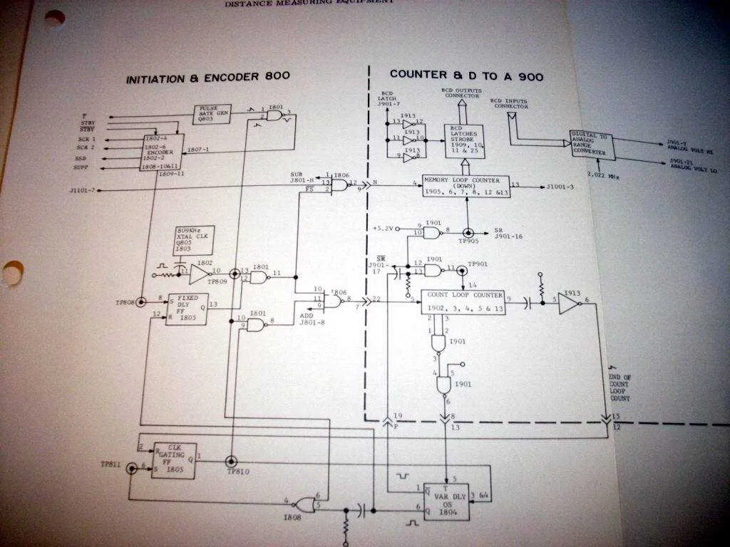
To effectively troubleshoot or design with the KDM-3 device, it’s crucial to study its circuit representation. This layout reveals the electrical connections and components that form the device’s core functionality. Begin by examining the power supply section, which plays a critical role in ensuring the correct operation of the entire system. Understanding voltage sources, grounding, and the distribution of power across components will help prevent common issues such as power instability.
Next, pay attention to the control circuitry, which manages the operational flow. Identifying the key elements like resistors, capacitors, and integrated circuits that control signal paths will enable you to optimize performance. If you encounter irregular behavior or need to modify the system for specific needs, focusing on these components can yield the best results.
In addition, signal processing blocks within the layout are vital for achieving accurate outputs. Reviewing how input signals are routed through various stages before reaching the final output stage ensures minimal distortion and noise interference. Whether you’re troubleshooting or improving the design, a clear understanding of the signal flow is indispensable.
Finally, a systematic analysis of the device’s interconnections is essential for pinpointing faults. Understanding how components are interconnected, whether through direct or indirect paths, will assist in identifying potential short circuits or component failures early in the diagnostic process. Ensuring that all connections are secure and correctly implemented is the key to maintaining long-term reliability.
Kdm-3 Circuit Overview
To ensure proper functionality, carefully examine the power connections and grounding layout. The key components, including resistors and capacitors, should be placed according to their designated values to avoid performance issues. Check the orientation of diodes and transistors to guarantee they are connected in the correct direction, as improper installation may lead to malfunction. The connections between each block should be verified for continuity, as broken or loose connections will result in system failure. Additionally, ensure that the voltage ratings of capacitors align with the expected operating conditions to prevent overheating and damage.
When troubleshooting, focus on checking the voltage at each node in the circuit to confirm whether it matches the expected values from the design. A significant deviation in voltage levels can indicate issues with power regulation or component failure. Use a multimeter to measure both AC and DC signals in the relevant sections of the circuit. Pay attention to the feedback loop, as any distortion or interruption in signal flow can impact the entire device’s performance.
For efficient repair, document any modifications or changes made during testing, as this helps track potential issues and avoid repeating errors. Always double-check resistor placements, as they directly affect the current flow through the system. Lastly, consider the heat dissipation needs of high-power components; appropriate heat sinks must be applied to prevent thermal stress.
Understanding the Core Components of the Kdm-3 System

The system’s central unit integrates several key modules that operate together to ensure high efficiency. Focus on the power supply and control interfaces when evaluating performance.
Power Module: This component manages voltage regulation and distribution. It’s crucial to select a unit that offers stable output under varying load conditions to avoid system instability.
Signal Processor: Handles the incoming data streams, processing and routing them to the appropriate subsystems. Pay attention to processing speed and data integrity for optimal performance.
Control Circuit: It governs the operation of the system’s various parts based on the processed signals. Ensure it has fault tolerance and the ability to handle communication errors seamlessly.
Input/Output Ports: These provide the necessary connectivity for integration with other equipment. Ensure the ports are compatible with the required communication standards and have sufficient bandwidth.
Protection Mechanisms: Incorporate safety features such as overcurrent and overheating protection. These prevent damage to the system from external or internal failures.
For the best results, ensure that each component is tested thoroughly for compatibility and performance under real-world conditions.
How to Interpret the Kdm-3 Schematic for Troubleshooting
Start by identifying the power input section. Verify the voltage levels using a multimeter and check for any discrepancies. Ensure that all power rails are correctly energized. If there’s no power, trace the connections back to the power supply unit for potential issues like a blown fuse or damaged components.
Next, focus on signal flow. Identify key components such as resistors, capacitors, and transistors in the signal path. Confirm that signals are reaching all the required points. If a signal isn’t present, inspect the component values and check for any short circuits or open paths.
When working with complex components like integrated circuits, refer to their pinout in the documentation. Cross-check each pin’s function against the actual voltages you’re reading. An incorrect voltage on any pin typically signals a faulty component.
For components with multiple connections, like buses or ground traces, ensure proper continuity. An interrupted trace can lead to erratic behavior. Use a continuity tester to confirm connections between ground and relevant points.
Verify the orientation of polarized components such as diodes and capacitors. Incorrect placement can cause malfunction or permanent damage. Double-check component positions, especially when replacing parts.
Finally, after replacing faulty parts, test the circuit step-by-step. Measure voltages at critical points to ensure the system is functioning as expected. If problems persist, refer back to the connections and components in the signal path, as they are often the source of the issue.
Step-by-Step Guide to Modifying the Kdm-3 Circuit Diagram

To modify the original layout, follow these steps for optimal results:
- Identify key components: Focus on the power supply, capacitors, and resistors. These sections are typically the most customizable for performance adjustments.
- Check the current path: Review the flow from the input to the output. It’s crucial to map out the current layout to avoid circuit conflicts when introducing new elements.
- Isolate modification areas: Determine where changes will have the least impact on overall functionality. Common modifications include altering signal paths or upgrading components for better efficiency.
- Substitute components: Swap resistors for higher precision or capacitors for enhanced filtering. Ensure all replacements match the power ratings of the original parts to prevent overheating or failure.
- Test each modification: After making changes, measure voltage and current across critical points to verify stability. This will help identify potential issues early.
- Optimize for space: Use smaller components or re-route paths to improve compactness without sacrificing performance.
- Verify with simulation: Before finalizing the changes, simulate the modified circuit to confirm expected behavior. This minimizes trial-and-error during physical testing.
Make sure to document each step thoroughly for future reference and troubleshooting. Adjusting the layout requires patience, but careful, incremental changes will lead to improved circuit performance and reliability.