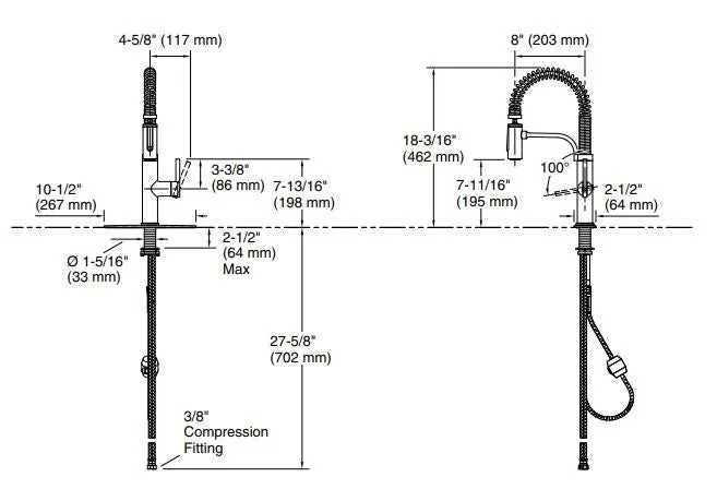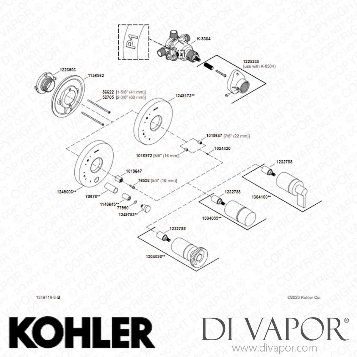
Start by identifying the main assembly elements: the spout, cartridge, handle, and mounting hardware. Understanding the placement and function of each component helps streamline maintenance or replacement tasks.
Cartridge units control water flow and temperature regulation; selecting the correct model is crucial for optimal operation. When inspecting the handle mechanism, verify if it uses a single or dual lever setup to match compatible replacements.
For secure installation, check the condition of washers, O-rings, and nuts that prevent leaks and ensure stability. Mapping out these elements according to their position beneath the sink or on the fixture itself aids in accurate troubleshooting and ordering.
Reference illustrations that label each part with numbers or names simplify the identification process, especially when coordinating repairs or upgrades. This systematic approach reduces downtime and avoids purchasing incompatible pieces.
Assembly Overview for Kohler Sink Mixer Components
Identify the main body housing the valve cartridge responsible for water flow control. The aerator, attached to the spout tip, ensures smooth water stream and prevents splashing. The handle lever connects directly to the valve stem, enabling temperature and pressure adjustments.
The spout includes an internal swivel joint allowing rotation for user convenience. Beneath the sink deck, the mounting hardware secures the fixture firmly in place. Supply lines attach to the inlet connections, providing hot and cold water delivery.
O-rings and seals are positioned at junctions to prevent leaks. Check the spray hose assembly, which integrates with the pull-out or pull-down spray head, often containing a check valve to stop backflow. Replace washers inside the cartridge if flow inconsistencies occur.
When servicing, consult the exploded view schematic illustrating each component’s placement and order, ensuring proper reassembly and part compatibility.
Identifying Key Components in Kohler Faucet Diagrams
Start by locating the cartridge assembly, as it controls water flow and temperature regulation. It often appears as a central cylindrical piece connected to the handle mechanism. Recognizing this component is essential for troubleshooting leaks or inconsistent water pressure.
Next, focus on the valve body, which acts as the main housing for water channels. It usually connects directly to the supply lines and serves as the foundation for other internal elements.
Inspect the aerator, positioned at the end of the spout, designed to mix air with water to reduce splashing and conserve usage. Its detailed illustration helps identify potential clogging points.
Check the spout and its mounting hardware, often displayed separately to clarify installation steps. Understanding its connection to the valve body aids in proper reassembly or replacement.
Identify the handle components, including the lever, screws, and decorative caps, which control water release. These are commonly shown exploded to highlight each piece’s function and order.
Pay close attention to washers, O-rings, and seals, small but crucial elements depicted near joints and moving parts. They prevent leaks and maintain smooth operation.
Finally, locate supply connectors and mounting nuts, which anchor the assembly to the sink. Clear identification of these ensures secure installation and proper alignment.
How to Use the Parts Diagram for Faucet Repair and Replacement

Start by locating the exact model number stamped behind the spout base or underneath the sink deck. Match it precisely with the schematic provided by the manufacturer’s support site.
Identify each component by its reference number. Cross-check the exploded view with your fixture to confirm the version. Variants may include cartridge types, diverter valve styles, or aerator thread specifications.
Turn off the water supply before disassembly. Use the chart to determine tool size–some assemblies require a 3/32″ hex key, others a flat-head screwdriver or adjustable wrench.
Pinpoint worn or damaged mechanisms such as O-rings, bonnet nuts, or the mixing valve. Reference their part codes to avoid ordering incorrect items. For instance, GP77005 is not interchangeable with GP1016515 despite visual similarity.
Check for update kits listed alongside the layout. Some older assemblies have retrofit options that simplify installation or improve durability.
Once replacements arrive, use the sequence shown to reassemble. Follow torque specs if listed–over-tightening the mounting nut or handle screw can cause fractures or leaks.
Compare your reassembly to the chart to ensure alignment. A reversed check valve or misfitted retainer clip will compromise flow or cause internal wear.
Common Components and Their Functions Explained
Replace the cartridge immediately if the handle becomes stiff or starts dripping. It controls water flow and temperature through a pressure-balancing mechanism. Models use ceramic discs or rubber washers, depending on the assembly year.
- Valve Cartridge: Regulates both hot and cold flow. Identified by model number stamped on the side.
- O-Rings: Prevent leaks at swivel joints and spout base. Replace during any disassembly to avoid rework.
- Aerator: Screwed into the tip; limits flow to 1.5–2.2 GPM. Clogs from hard water are common. Clean monthly.
- Diverter: Redirects stream to sprayer. Malfunction causes weak pressure or backflow. Access under spout collar.
- Mounting Hardware: Includes lock nut, washer, and threaded shank. Check tightness annually to prevent wobble.
- Spray Hose: Nylon-braided for pull-down units. Look for leaks near couplings. Avoid kinks to extend lifespan.
- Check Valves: Prevent cross-contamination between hot and cold lines. Required by code in certain states.
Match each replacement to the product number printed under the escutcheon or in the original installation manual.