To ensure safe and efficient operation of your water recreation setup, it is crucial to follow industry-standard electrical configurations. Start by securing proper grounding for all components, such as pumps and filtration units, to avoid any risk of electric shock. Utilize GFCI breakers in all circuits related to water equipment to immediately cut power in the event of a fault, preventing potential hazards.
Next, pay close attention to the correct voltage and amperage ratings for all connected devices. High-powered machines like pumps or heaters often require dedicated circuits with a separate breaker to ensure they are adequately protected from overloads. Properly dimensioning the wire gauge is essential for minimizing power loss and preventing overheating. For most residential applications, a 12 AWG wire is typically sufficient for smaller systems, but larger installations may require thicker cables, such as 10 AWG or even 8 AWG.
Ensure that all components are placed in accordance with local building codes, particularly when routing cables near water features. The distance between the control panel and equipment should be minimal to reduce voltage drop. Also, always check for compliance with relevant electrical codes to ensure safe installation. Investing in quality materials and professional installation will safeguard the longevity and safety of the entire system.
Electrical Setup for Pool Systems

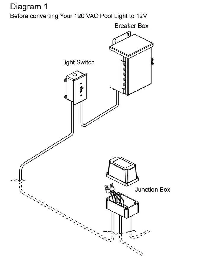
Ensure proper grounding of all electrical components connected to aquatic facilities. All electrical circuits should be protected by a GFCI (Ground Fault Circuit Interrupter) breaker, especially those linked to filtration pumps, heaters, and lighting. Use waterproof junction boxes to house connections that may be exposed to moisture. Verify that all wiring is rated for outdoor use and can withstand exposure to humidity and temperature changes.
Power to pumps, heaters, and lights should be distributed through a dedicated circuit, with the appropriate gauge wire for the amperage rating of each component. Ensure that each system is individually fused or circuit-protected. Electrical components should be installed at least 5 feet away from water features to prevent the risk of short circuits.
Install a manual disconnect switch near the filtration equipment to allow for easy maintenance and emergency shut-off. Use wire that complies with local code standards, typically copper or aluminum, and ensure all connections are tightly secured and insulated. For remote control systems, use low-voltage cabling that meets safety requirements for outdoor use.
Always double-check that all connections are secure and that there is no exposed wire that could lead to shocks or shorts. Keep all switches and outlets above the waterline and properly sealed to prevent water ingress. Periodically inspect and test all systems to ensure continued safe operation.
Choosing the Right Electrical Components for Pool Equipment

To ensure safety and reliable operation of your aquatic systems, selecting high-quality electrical parts is crucial. Here’s what to focus on:
- Circuit Breakers: Use a dedicated GFCI (Ground Fault Circuit Interrupter) breaker for each major device, such as pumps or heaters. This will protect the system from electrical surges and prevent potential hazards.
- Wire Gauge: For pumps or other heavy-duty equipment, use copper wires with sufficient amperage capacity. For example, a 1 HP pump typically requires a 12 AWG wire, while larger pumps might need 10 AWG.
- Conduit: Install non-metallic conduit, such as PVC, to protect wiring from external damage. It’s resistant to moisture, UV rays, and physical wear, ensuring long-lasting performance.
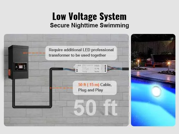
- Transformers: For low-voltage lighting or automated systems, choose a transformer that matches the required voltage and load. An overpowered transformer can damage sensitive equipment, while an underpowered one may not function optimally.
- Disconnect Switches: Each high-voltage piece of equipment should be connected to an easily accessible disconnect switch. This ensures you can safely turn off power for maintenance or emergencies.
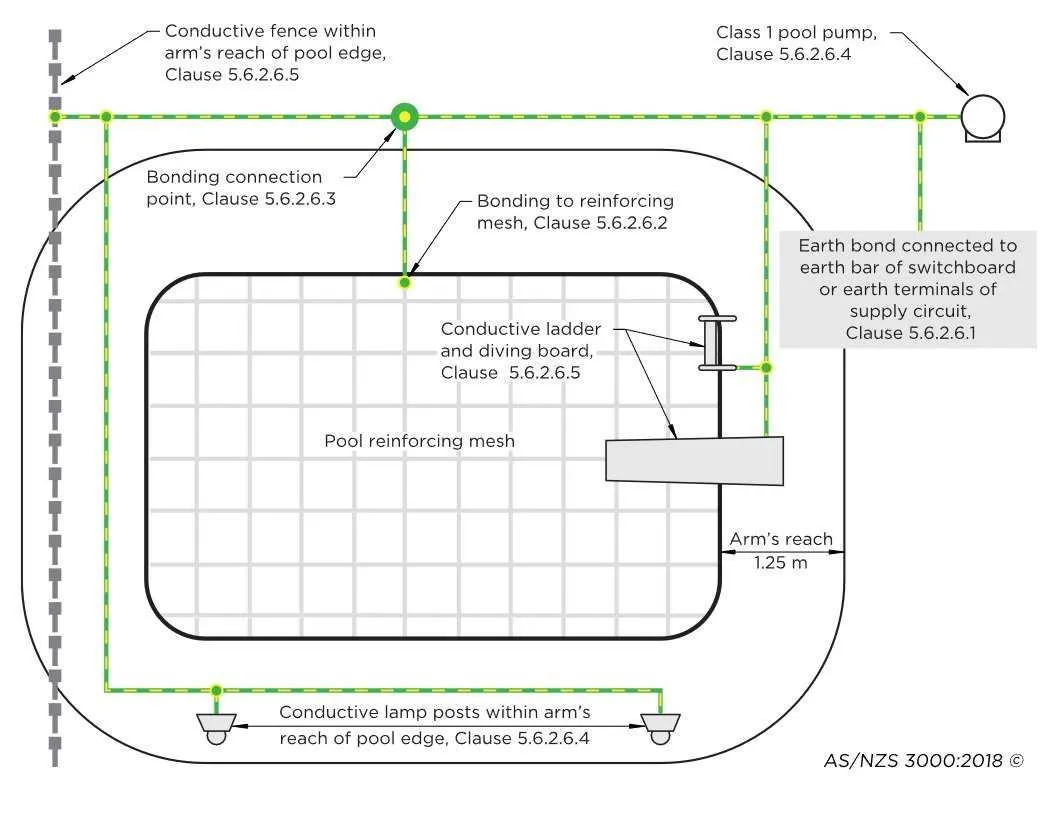
- Grounding: Ensure that all metallic components are properly grounded. This prevents electrical shock risks and complies with local safety standards.
By focusing on these specific components, you can enhance the safety, efficiency, and longevity of your equipment setup.
Wiring the Pump and Filtration System Safely
Ensure all connections are made according to local electrical codes to prevent hazards. Use a dedicated circuit breaker rated for the pump’s motor to prevent overloading. Make sure the power supply is isolated before installation. For the filter system, ensure proper grounding of all metallic components to prevent electrical shock. Avoid running power lines near water or moisture-prone areas; instead, use conduit that is waterproof and rated for outdoor use.
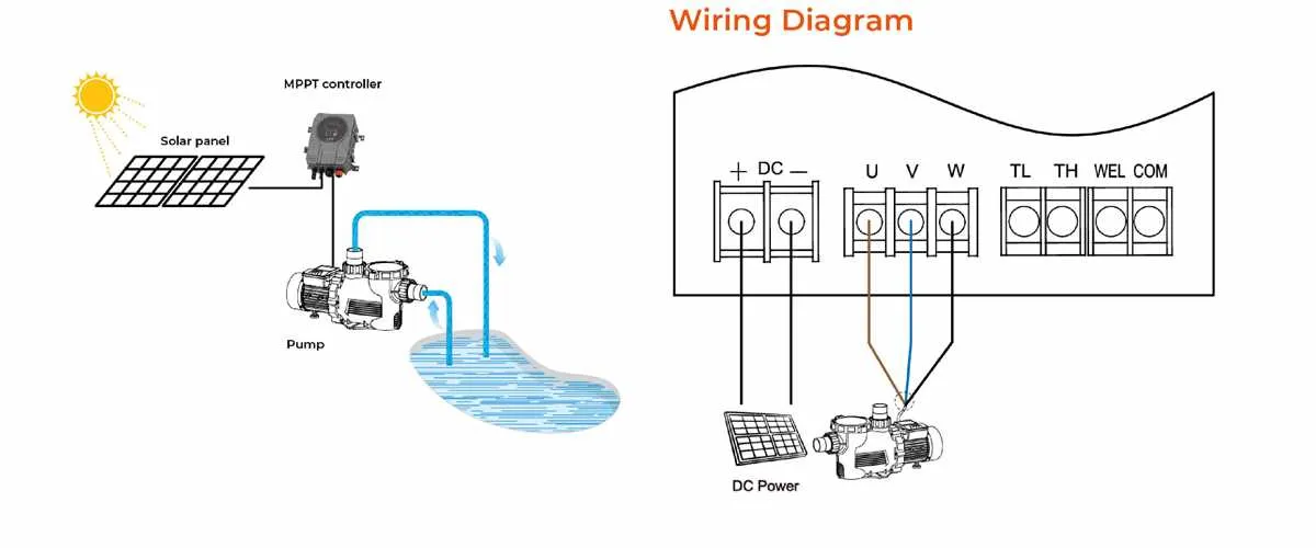
Use a correctly sized cable that matches the pump’s electrical requirements, ensuring it is rated for outdoor exposure and resistant to UV damage. Always install a disconnect switch near the equipment for emergency shutoff. Use double-pole breakers for 240V systems and single-pole breakers for 120V, matching the motor’s voltage specifications.
Position the pump and filter system at least 10 feet from the water’s edge to minimize the risk of electrical hazards. Ensure that all equipment is installed on a dry, level surface, and avoid any areas where water could pool around electrical connections. Confirm that all connections are tightly secured to prevent any loose or exposed wires that could lead to short circuits.
Regularly inspect the system, especially after storms or maintenance, to ensure all electrical components remain in good working condition and there are no signs of wear or corrosion on connections. Proper maintenance and attention to detail during installation will significantly reduce the risk of malfunction or safety issues.
Connecting Lighting and Heater to Electrical Circuit

Ensure that the circuit breaker is rated appropriately for the combined load of both the heater and lighting system. Typically, the breaker should be rated for at least 20-30% higher than the total amperage draw of both devices. Use a dedicated circuit for each appliance to avoid overloads and ensure safety.
For the heater, use a heavy-duty cable (12 AWG or thicker) to handle high current flow. The wire should be run directly from the breaker panel to the heater, ensuring proper grounding and insulation. The heater should be connected to a Ground Fault Circuit Interrupter (GFCI) to prevent electric shocks, especially in wet environments.
Lighting fixtures typically require a 14-16 AWG wire, depending on the wattage of the bulbs used. If connecting multiple lights, use a junction box to distribute power evenly. Ensure all connections are made using waterproof connectors to prevent corrosion and short circuits due to exposure to moisture.
When running the cable through the conduit, ensure it is rated for outdoor use and capable of withstanding direct burial if necessary. Secure all cables and connections with waterproof tape and clamps to prevent movement that could cause wear or damage over time.
Verify all connections are tight and that no wires are exposed. Always double-check the grounding of all devices to avoid electrical hazards. Once the connections are complete, test both the heater and lights for proper function before finalizing the installation.