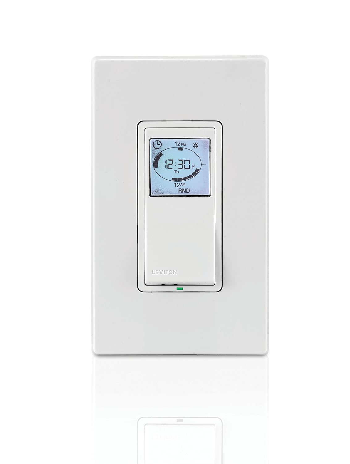
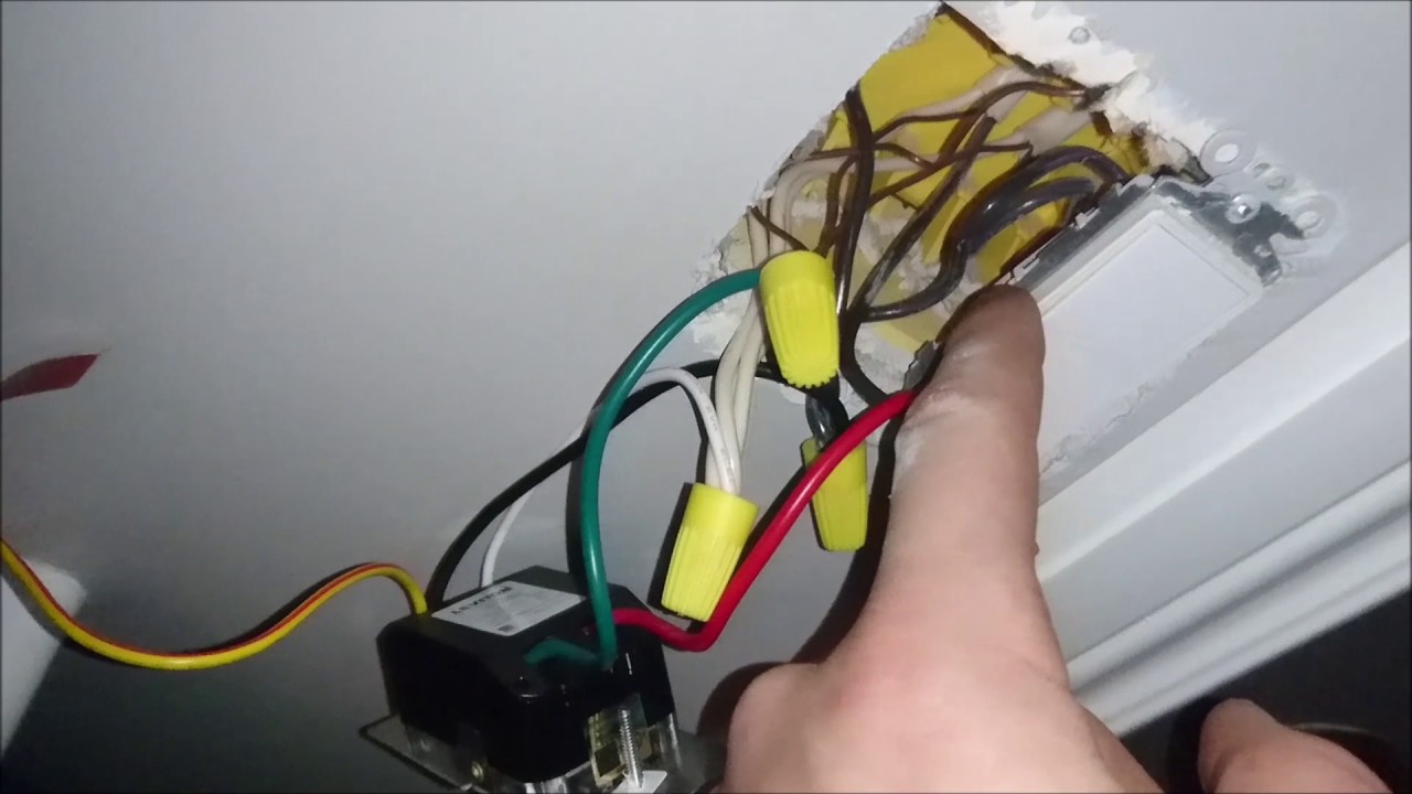
Vizia+ 24 hour Timer VAC, 60HZ, W Incandescent, 15A Resistive/ Inductive, 1HP, for single pole, 3-way or more locations, with astronomic clock, backlit. Remove wires from switch and separate. Turn power back on.

Using ordinary tester, test each black wire to bare copper ground wire. Only one. Vizia+ 24 hour Timer VAC, 60HZ, W Incandescent, 15A Resistive/ Inductive, 1HP, for single pole, 3-way or more locations, with astronomic clock, backlit.
The VPT24, using the single pole wiring diagram indicates I need to connect a black (hot) wire, a white neutral wire, a green ground wire, and a red load wire. I’m trying to hook up my VPTP timer on a three way system.
the big problem is on both switches already installed i only have three wires.Get Leviton VPTPZ Instructions / Assembly. Get all Leviton manuals! ManualShelf.
Sign Up. Sign up to create an account Facebook Twitter.
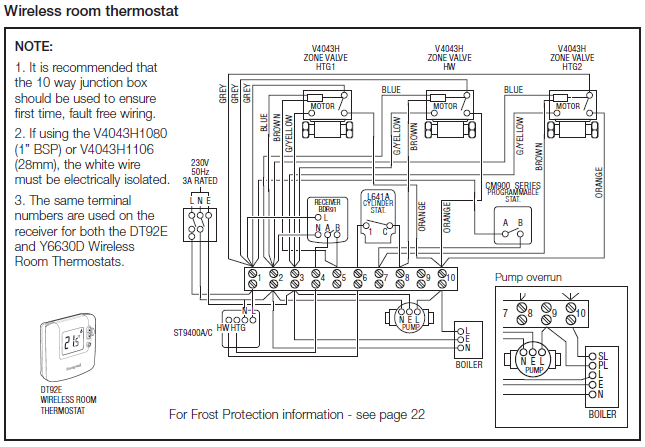
or. By clicking Create Account, you agree to the Company’s Connect wires per WIRING DIAGRAM as follows: • Green or bare copper wire in wall box to timer switch Green lead.
So, the hot wire from your electrical panel (supplies power to the device) goes to the black lead of the VPT24 The neutral goes to the white lead. The wire that carries power to the light you wish to operate attaches to the red lead.
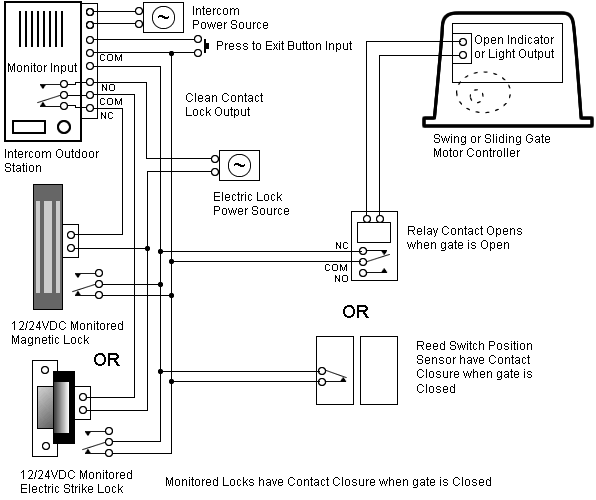
Leviton Decora Three Way Switch Wiring Diagram Acquire the Leviton 15 amp 3-Way Duplex Switch RWS, Anyway, the instructions on the box (and identical on Leviton site) don’t bother to say. Leviton 3 Way Switch Wiring Diagram. Single Pole Switch Wiring Diagram. Leviton 4 Way Switch Wiring Diagram.
3 Way Switch. Leviton 3 Way Switch Wiring. WIRING TIMER SWITCH: Connect wires per WIRING DIAGRAM as follows: • Green or bare copper wire in wall box to timer switch Green lead.
• Line Hot wall box wire to timer switch Black lead. • Load wall box wire to timer switch Red lead. • Line Neutral wall box wire to timer switch White lead.
The VPT24, using the single pole wiring diagram indicates I need to connect a black (hot) wire, a white neutral wire, a green ground wire, I’m trying to install a Leviton VPTP Digital Timer Switch for an exterior porch light. The only wires I have in the box as its the end of the circuit are WHITE and BLACK and obviously a ground.LEVITON VPT24 INSTALLATION INSTRUCTIONS Pdf Download.Leviton VPTPZ : Instructions / Assembly
