For quick identification of key elements in the LG model WM8000HWA, refer to the detailed schematic layout showing each integral unit and assembly. This resource enables precise location and recognition of mechanical and electronic modules critical for troubleshooting or replacement.
Focus on the control panel assembly, drum components, and internal valve structures which often require maintenance. Clear labeling within the visual reference aids in distinguishing between similar connectors and fasteners, streamlining repair tasks.
Use the layout to confirm part numbers before ordering replacements, ensuring compatibility and avoiding common installation errors. The guide’s stepwise mapping supports both professional technicians and experienced users in efficient service operations.
LG Washer WM8000HWA Parts Diagram
Locate the detailed schematic for the LG WM8000HWA directly through the manufacturer’s service manual or authorized repair websites. This blueprint outlines the internal components such as the motor assembly, control board, water inlet valves, and suspension springs with precise labeling for easier identification.
When replacing a specific element, cross-reference the model number and component code to ensure compatibility. Focus on diagrams that break down the drum, pump, and detergent dispenser sections separately for targeted troubleshooting.
For quick access, downloadable PDF versions from trusted appliance parts retailers often include exploded views, showing how each piece connects and fits. This facilitates accurate ordering and installation, minimizing errors during maintenance.
Use color-coded illustrations if available, as they enhance clarity when differentiating electrical wiring, hoses, and mechanical linkages. This approach supports efficient diagnosis and component swaps without guesswork.
Always verify the diagram’s revision date matches your unit’s production year to avoid discrepancies caused by design updates or manufacturing changes over time.
How to Identify Key Components in the LG WM8000HWA Assembly Illustration
Focus on major mechanical and electrical elements first: Locate the drum, motor, and suspension system as primary structural parts. These form the core of the unit’s function.
Next, examine the control panel section. It includes the electronic control board, selector knobs, and display interface. Identifying these aids in troubleshooting operational issues.
Pay attention to water inlet valves and drain pump assemblies. Their positions are typically marked near the rear or bottom of the schematic and are vital for fluid management.
Note the door lock mechanism and gasket assembly. These are essential for safety and water containment, usually highlighted around the front access area.
Use component labels and part numbers provided in the illustration to cross-reference with the manufacturer’s service manual for precise identification and ordering.
Finally, verify the arrangement of wiring harnesses and connectors. Their routing is crucial for proper electrical connections and diagnostics.
Common Replacement Components for LG WM8000HWA and Their Locations

Key elements that often require substitution include:
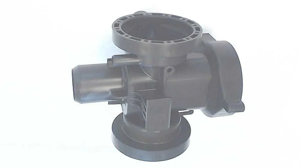
- Drain Pump: Located at the bottom front of the unit, accessible by removing the lower access panel.
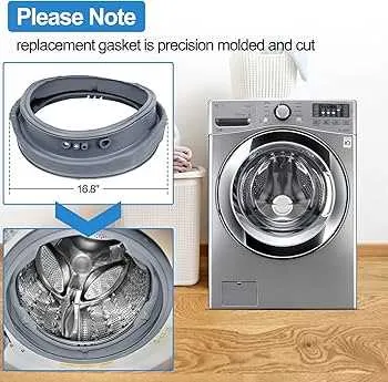
- Door Seal (Gasket): Surrounds the door opening, ensuring a watertight closure; removal involves detaching the front panel and door assembly.
- Control Board: Positioned behind the control console at the top front; replacement requires removing the top panel.
- Water Inlet Valve: Situated at the rear, connected to the water supply hoses.
- Drive Motor: Found at the base of the appliance, secured behind the rear panel and connected to the drum.
- Door Lock Assembly: Mounted near the door latch inside the front panel; critical for safety and cycle operation.
- Suspension Springs and Shock Absorbers: Located inside the cabinet, connected to the drum and frame to stabilize movement during cycles.
- Drain Hose: Runs from the drain pump to the back of the machine; inspect for clogs or damage.
For replacements, verify model compatibility and follow disassembly instructions carefully to avoid damage. Always disconnect power and water before servicing.
Using the Parts Diagram to Troubleshoot WM8000HWA Washer Issues
Identify the faulty component by matching the error symptoms with the schematic. For example, if the appliance fails to spin, locate the clutch assembly and motor coupler within the exploded view to check for wear or damage. Refer to the illustration to find exact part numbers and their position relative to adjacent mechanisms.
Use the layout to verify electrical connections and harness routing. This helps detect loose or disconnected wires causing operational failures. Cross-reference the visual guide with the control board and sensors to ensure proper signal flow.
When leaks occur, pinpoint seals, gaskets, and hoses shown in the detailed breakdown. Inspect these elements physically, guided by their placement in the technical sketch, to replace compromised units efficiently.
For unusual noises, focus on components involved in drum movement and suspension. The exploded view reveals shock absorbers, bearings, and pulleys that should be examined for degradation or misalignment.
Utilize the schematic for accurate reassembly after part replacement. Follow the sequence and orientation of each piece to avoid installation errors that might lead to malfunctions.