Ensure the proper connection of safety components by following these steps for reliable performance. Begin by identifying the terminals for each device, which should be clearly marked for ease of installation. The key to a successful setup lies in the correct alignment of the wires, where each connection must be secure to maintain functionality.
Connect the power lines carefully, ensuring that they match the designated input channels. The safety system relies on a stable flow of energy to operate correctly, so any loose or incorrectly placed wires can lead to malfunctions. Double-check each connection, confirming that the wires are fully inserted into the terminal blocks.
Next, pay attention to the signal wire configuration. Properly connecting the output lines is crucial for seamless communication between the devices and the control unit. Test the connection by activating the system and confirming the expected response. If there are any issues with alignment or interference, recalibrate the setup.
Finally, after securing all connections, conduct a full system test to ensure that all components interact as expected. This step is essential for avoiding future operational errors and ensuring the safety features function as intended. Make sure the installation is compliant with the manufacturer’s guidelines for optimal results.
Proper Connection for Safety Devices
Ensure the correct alignment of the safety components to guarantee optimal performance. If the system doesn’t react as expected, check the following:
- Verify the polarity of the wires–incorrect connections can prevent proper operation.
- Check for any damage to the cables, including fraying or exposed wires, as these could lead to malfunction.
- Ensure that all connections are tight and secure, avoiding any loose contacts that may cause intermittent failure.
- For systems with multiple components, confirm that each device is correctly linked, with proper routing of the cables to avoid signal interference.
- Inspect the alignment of the components. Misalignment can lead to false signals or failure to trigger the system.
If the issue persists, replace the affected parts with compatible models to restore full functionality. Regular checks and maintenance of the system will help prevent future issues.
Understanding Sensor Connections in Liftmaster Systems

Ensure the correct polarity when connecting the control unit to the photo eye pair. The positive terminal should always be connected to the signal output from the opener, while the negative terminal should connect to the ground. Double-check for any potential miswiring, as this could prevent proper communication between the components.
When positioning the devices, place them facing each other at the same height and within the recommended range to guarantee reliable performance. A misaligned setup can result in signal failure, preventing the opener from responding correctly to interruptions.
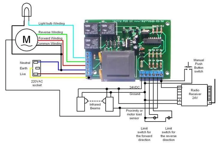
If the setup involves multiple devices, use the designated connection points on the central control module to ensure proper communication. It’s vital to adhere to manufacturer instructions for terminal locations, as incorrect placement can lead to faults in operation.
Test the system by manually obstructing the pathway between the units. If the opener fails to respond, check for any physical damage to the lines or devices, and inspect for interference from nearby electrical sources that could affect signal clarity.
Important Tip: Always use high-quality cables to avoid voltage drop or interference, which can disrupt the signal transmission.
Common Wiring Issues and Solutions for Sensors

If your door opener isn’t responding properly, first check for any loose or disconnected wires. Broken or improperly connected cables can easily cause intermittent signal loss. Inspect both ends of the cables to ensure they are securely connected to the control board and the device itself.
Misalignment of the devices can also lead to malfunctioning. Ensure both units are properly aligned, and there is no obstruction between them. If necessary, adjust their positioning and double-check for any visual indicators of misalignment.
Dirty connections or damaged terminals may result in poor communication between components. Clean any corrosion or dirt on the terminals with a soft cloth and, if necessary, use a contact cleaner. Replace any damaged connectors immediately to prevent further issues.
Another common issue is power surges. A sudden increase in voltage can burn out internal components. Install a surge protector or use a dedicated circuit to avoid damage to delicate parts. If there’s no response from the system, check the fuse or circuit breaker and reset or replace it as needed.
Faulty cables are often the root cause of poor performance. If you notice signal issues or inconsistent functionality, consider replacing the cables entirely. Choose cables with a thicker gauge for better signal strength, ensuring reliable operation across longer distances.
Incorrect polarity can also disrupt operation. Verify that the positive and negative wires are connected correctly to avoid electrical issues and damage to the system.
Step-by-Step Guide to Connecting the Safety Sensors
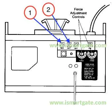
Start by ensuring the power to the opener is turned off to avoid any electrical hazard. Locate the two terminals on the motor unit where the wires will be attached. One terminal is for the common (ground) wire, and the other for the live wire.
Next, take the wire that will connect to the ground terminal and attach it securely. Ensure there is no exposed wire that could lead to a short circuit. For the live wire, make sure it is firmly twisted and inserted into the correct terminal. Use a screwdriver to tighten the terminal screws, making sure the connection is solid.
After the main connections are made, proceed to mount the separate components. Install the receiver and emitter on opposite sides of the garage door. The components should be positioned at an equal height, usually around 6 inches off the floor, ensuring that they align properly with one another.
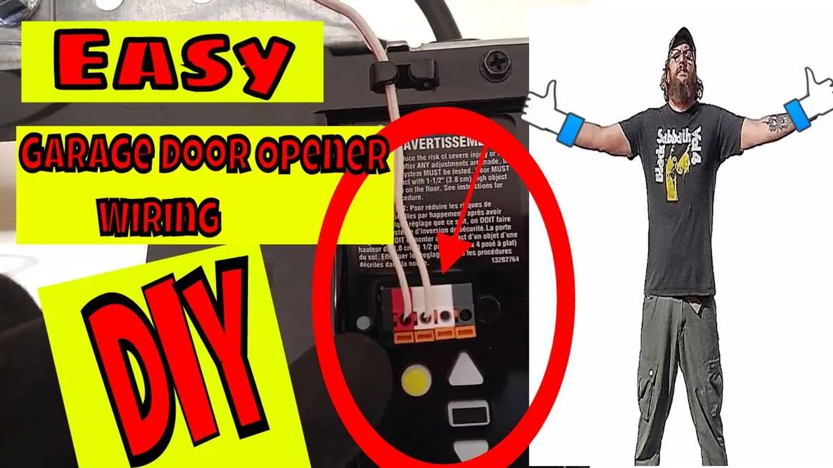
Connect the terminals from both the emitter and receiver to the motor unit, matching the wiring colors: typically black for the ground and white for the live wire. Again, ensure the connections are tightly secured to prevent any loose wiring that could lead to malfunction.
Once all connections are complete, double-check for any exposed wire or incorrect terminal placement. Power on the opener and test the system by blocking the sensor’s path to verify the door reverses direction as expected. If the system functions properly, you have successfully completed the setup.
Tip: Always use high-quality wire and connectors to ensure long-lasting performance and avoid potential issues in the future.