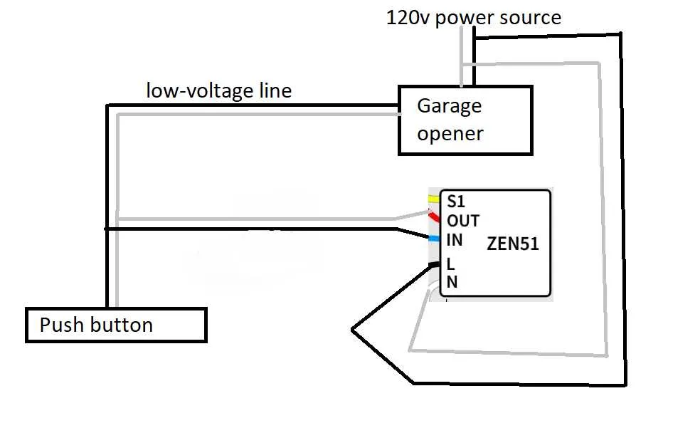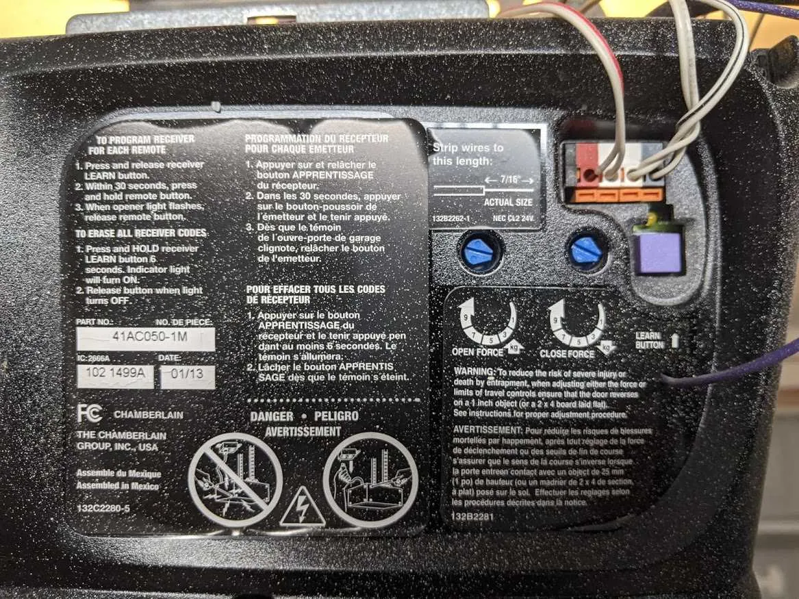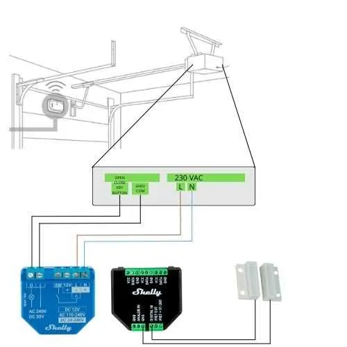
Ensure proper installation by following the specific connections for a 4-wire setup in automatic entry systems. Focus on correctly pairing the conductors to prevent malfunctions and ensure smooth operation.
For an optimal connection, connect the two main conductors for power, ensuring that the voltage aligns with system requirements. Use the additional two for communication or control signals, each properly isolated to prevent interference.
Key Steps: First, identify the power terminals and securely attach the corresponding wires. Then, connect the control signal lines to the designated terminals, ensuring clear paths for communication between components. Double-check the connections to ensure they’re tight and properly insulated, avoiding short circuits.
Test the setup after installation to verify that the mechanism operates as intended. If the system fails to respond, check for any loose connections or incorrect pairings between signal and power lines.
Tip: Always use wires rated for the specific voltage to avoid overheating and potential damage to your equipment. Prioritize quality insulation to extend the lifespan of the system.
4-Connection System Setup

To ensure a proper connection for your device, follow these steps. First, connect the power source to the main terminal. Use the specified connectors to link the motor to the control system, ensuring a solid connection. Attach the two additional terminals for safety and signal transmission. Verify that all connections are secure and insulated before powering on the system.
Next, check for any visible signs of wear or loose connections. Ensure that each link is appropriately fastened to avoid signal interference or power loss. For systems with limited space, consider using compact connectors that fit within the allocated space without causing strain on the components.
For troubleshooting, use a multimeter to test voltage and continuity at each terminal. This helps identify any disruptions in the flow of power or signal. Regular maintenance should include inspecting for corrosion or damage at the contact points.
Understanding the Basic Components of a 4 Wire System

When working with a 4 wire setup for automated entry systems, it is important to understand the key components that play a role in operation.
- Power Source: This is the primary energy supply for the system. It is responsible for powering the entire mechanism, providing the necessary voltage to drive the motor and control the system.
- Control Mechanism: The controller directs the functions of the system, such as opening or closing. This component uses signals sent through the connected lines to initiate movements or halt actions at the correct times.
- Sensor Elements: These are critical for detecting the position or status of the mechanism. They provide feedback to the controller, ensuring safe operation by detecting any obstructions or malfunctions.
- Movement Motor: The motor is the component that physically drives the mechanism’s movement. It relies on the electrical input from the control mechanism to activate its internal components.
Ensure that all connections are secure to avoid operational failures. Regular maintenance and troubleshooting of the system’s components will guarantee longevity and reliability.
Step-by-Step Guide to Wiring a 4 Wire Mechanism

Start by identifying the power source and ensure the circuit is off before connecting any components. The two primary conductors, typically red and black, carry current to the system. The green conductor is used for grounding, while the white one serves as a neutral path for current return.
First, connect the red and black wires to the corresponding terminals on the control unit. Make sure the connection is tight to prevent power loss. Next, attach the green conductor to the grounding terminal. This ensures safety by diverting any unwanted electrical flow to the earth.
Proceed to connect the white wire to the neutral terminal. This step is crucial for completing the return circuit. Afterward, double-check all connections, ensuring no loose or exposed ends that could cause a short circuit.
Once everything is securely connected, test the system by restoring power and operating the mechanism. If all functions run smoothly, the installation is complete. If any issues arise, inspect each connection and test continuity using a multimeter to confirm proper flow.
Troubleshooting Common Electrical Issues in 4-Wire Systems

Start by verifying the power source. Ensure that the circuit is properly connected to the main electrical panel and is providing adequate voltage. A multimeter will help confirm this. If there’s no power reaching the system, inspect the connection at the circuit breaker or fuse for any signs of damage or corrosion.
Next, check the connections at the terminals. Loose or poorly connected terminals can cause malfunction. Tighten any screws or bolts that might have come loose, but avoid over-tightening as it can lead to breakage or short-circuiting. Ensure that the contact points are clean and free from debris or rust.
If the system isn’t responding to commands, inspect the control board. Faulty relays or components on the board may disrupt functionality. In such cases, replacing the control board might be necessary. If you’re working with a manual switch, ensure it is properly connected and free from wear.
For systems using sensors, misalignment is a common issue. Ensure both the sensors are aligned correctly and that no obstruction is blocking the signal between them. Misalignment often results in the system not activating as intended. Make sure to check the sensor connections for any fraying or disconnection.
If there are any irregular movements or inconsistent behavior, inspect the motor connections. Inadequate contact can cause intermittent operation. Check for any frayed insulation or exposed parts that might be causing short circuits.
Lastly, examine the transformer. If the voltage is low, the motor may not receive enough power to function properly. If the transformer is malfunctioning, it will need to be replaced to restore normal operation.