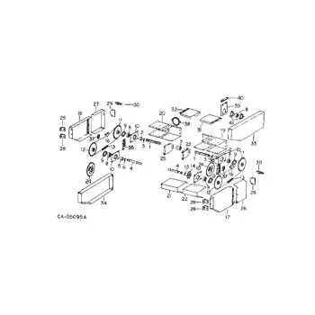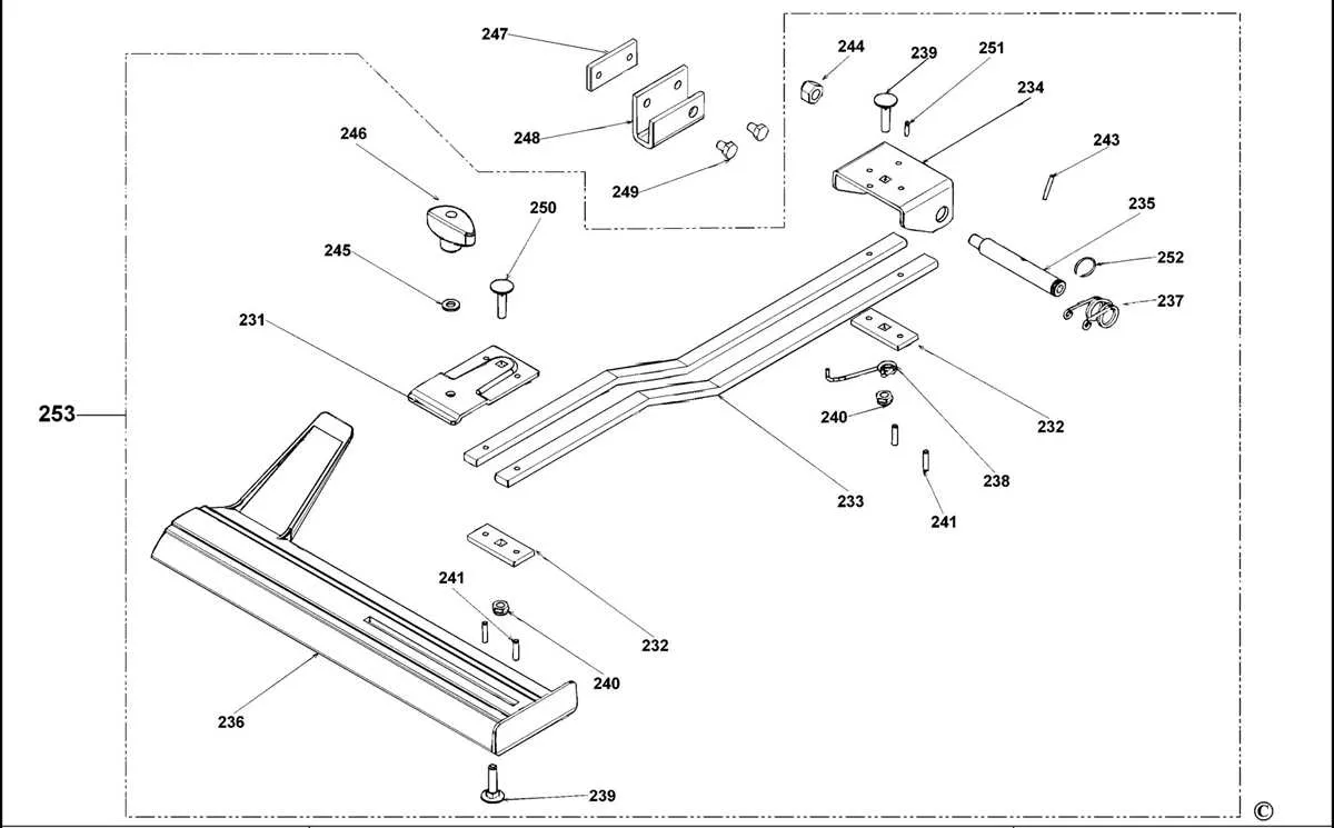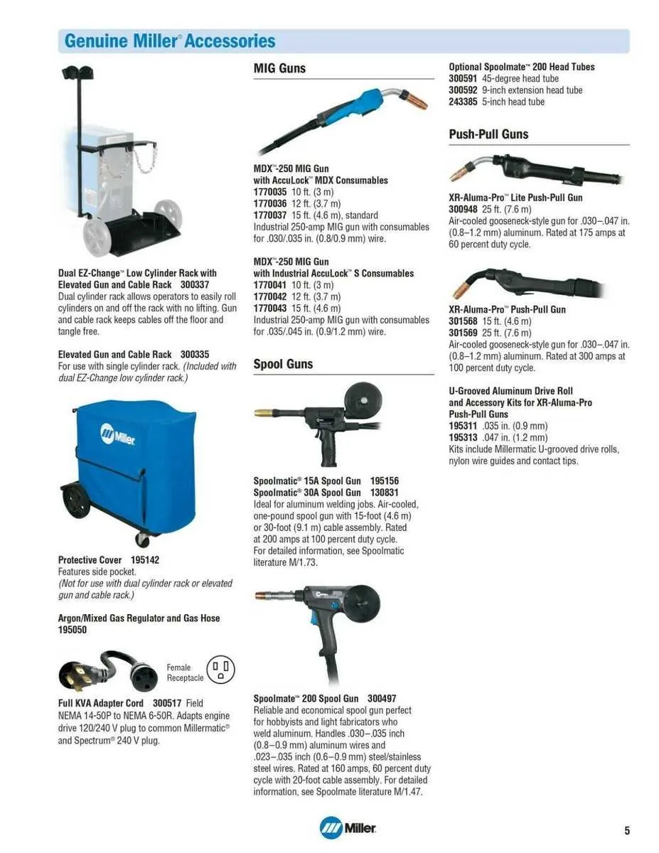
To ensure smooth operation and effective troubleshooting of your welding equipment, familiarize yourself with the detailed schematic of its core components. The schematic layout offers a precise view of the internal setup, helping you identify each part’s function and connection within the system.
Start by focusing on the power supply unit. It plays a crucial role in converting electrical input into the proper voltage, maintaining a steady current flow throughout the device. Next, examine the wire feeder assembly. This mechanism is responsible for consistently feeding the welding wire, which is essential for uninterrupted operation.
Don’t overlook the control board, which manages settings such as voltage, amperage, and welding mode. The layout of this system is fundamental for adapting the machine to various tasks, making it a pivotal element in achieving precise results. Be sure to also assess the cooling system components–keeping the unit at optimal temperature ensures both safety and longevity.
Understanding the arrangement and function of these key components can significantly enhance your ability to repair and maintain your equipment. Referencing the schematic allows for efficient identification of worn or faulty parts, minimizing downtime and costly repairs.
Understanding the Component Layout
To ensure optimal performance and easy repairs, always refer to the schematic for accurate component identification. The electrical system is divided into key sections: power supply, control circuits, and motor systems. Each section should be checked for signs of wear or damage during maintenance. Pay close attention to connectors and fuses; they are often the source of intermittent issues.
When troubleshooting, begin by locating the primary control board. This board interacts with various switches, relays, and sensors, all of which can impact operation. If you notice erratic behavior, inspect the relays first, as they can fail under high load conditions.
The wire feed assembly, which includes the motor and drive rollers, should be regularly cleaned and lubricated to maintain consistent performance. Over time, the rollers may wear, causing feeding issues. Check their alignment to prevent unnecessary strain on the motor.
Also, examine the cooling system carefully. The fan and thermal sensor play crucial roles in preventing overheating. If the unit overheats, it could be a sign that the fan is malfunctioning or that the sensor is not triggering the cooling process at the correct temperature.
Finally, ensure the grounding components are secure. Faulty grounding can lead to safety hazards and poor electrical performance. Always verify the integrity of grounding straps and ensure the system is connected to a proper earth point.
Identifying Key Components in the Millermatic 252 Parts Diagram
To effectively navigate the schematic, start by locating the main components involved in power supply, wire feeding, and welding. Focus on the transformer and rectifier sections, which handle the conversion of alternating current (AC) to direct current (DC). These parts are crucial for consistent performance.
The wire feeder motor is another key element to identify. This component regulates the feeding speed of the electrode wire, directly impacting the quality of the weld. Pay attention to the wire spool holder and its associated mechanism as it ensures smooth and uninterrupted wire delivery.
The contactor assembly, typically positioned near the power section, is integral to controlling the arc. Its operation affects the initiation and termination of the welding process. Check for any associated relays, as they manage the switching between operational states.
Examine the cooling system layout. The fan and heat sink are crucial for maintaining optimal temperature, preventing overheating during extended use. Keep track of the ventilation paths to ensure airflow is not obstructed.
Last but not least, review the electrical connections for proper alignment. Faulty wiring or connectors can lead to inconsistent performance. Ensure all ground connections are intact and securely attached to avoid short circuits or grounding issues.
How to Replace Worn Out Parts in the Millermatic 252

Start by unplugging the unit and disconnecting the gas cylinder. Use a 5/32-inch hex key to remove the side panel for access to internal assemblies. Always discharge any residual current before handling electrical components.
If the drive roll assembly is slipping or producing irregular wire feed, inspect the tension arm and bearing surfaces. Replace the drive rolls with matching groove sizes appropriate for your wire diameter–typically .030 or .035 inch. Ensure the shaft key is aligned during reassembly.
For a faulty contactor relay, locate the control board near the rear ventilation panel. Use a multimeter to verify continuity and swap the relay only with the OEM-rated 24V DC version. Avoid soldering directly to the board; use compatible connectors.
When the gun liner causes wire jams, disconnect the trigger lead and remove the front housing nut. Insert a replacement liner cut to the correct length, making sure the trimmed end is deburred to prevent feed issues. Reassemble with a new tip and nozzle if erosion is visible.
Replace a malfunctioning solenoid valve by detaching the gas hose and removing the retaining screws. Match the voltage and flow rate specifications–typically 24V with a 60 SCFH capacity. Use thread sealant on all fittings during reinstallation.
Reattach all panels, check connections, and test under load using a scrap metal coupon. Monitor amperage and wire speed for consistency. Keep a maintenance log with serial numbers of replaced elements for future diagnostics.
Understanding the Wiring and Electrical System of the Millermatic 252

Start by disconnecting the power source before accessing any internal electrical components to avoid shock or damage.
- Main Power Input: Confirm the voltage rating matches your facility’s supply–208/230V single-phase is standard. Verify correct wiring to the L1 and L2 terminals on the primary switch.
- Transformer Connections: Check all leads from the step-down transformer for signs of heat stress or discoloration. Replace any corroded spade terminals and confirm tightness of all fasteners.
- Contactor Assembly: Inspect the contactor for pitted or stuck contacts. Resistance across the coil terminals should fall within manufacturer specifications (typically 60–90 ohms).
- Control Circuit Board: Examine the PCB for cracked solder joints and failed capacitors. Common failure points include the relay driver and voltage regulation sections. Use a multimeter in diode mode for initial checks.
- Wire Feed Motor Circuit: Ensure proper voltage delivery (usually 24V DC) at motor input during trigger activation. Intermittent feed often traces back to loose board connectors or relay failure.
- Trigger Switch and Gun Leads: Continuity from the trigger to the control relay input should be uninterrupted. Inspect the gun lead harness for crushed insulation or exposed copper, especially near strain reliefs.
Refer to serial-specific schematics when tracing wires, as connector layout may vary between production runs. Label wires before disconnection and document pin positions with photos for reliable reassembly.