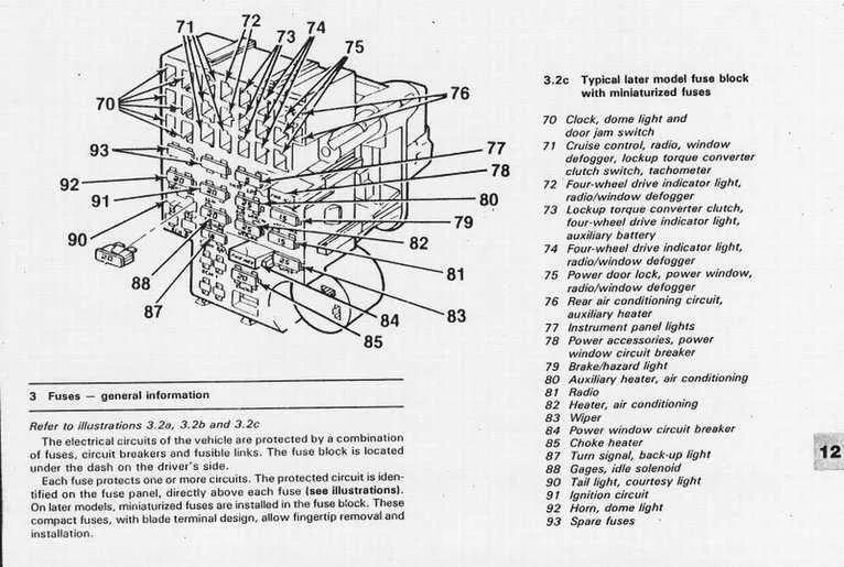
Start by checking the lower left section beneath the steering column–this is where the control unit is mounted on most General Motors light-duty models from the early ’80s. Access requires removal of the knee bolster and possibly the ashtray assembly. Once exposed, you’ll see labeled terminals for lights, wipers, and ignition circuits.
Tail lamp issues? Locate the terminal marked “TAIL LPS”–typically positioned in the second row, leftmost side. A blown 20A mini-blade unit is common here. For headlights and dash illumination, check the “HLR” and “INST LPS” slots respectively. If both are unpowered, inspect the headlamp switch and ground path behind the dash cluster.
Starter or horn not responding? These rely on high-amperage feeds. The “IGN” and “HORN” terminals are often protected by 25A and 20A elements. Use a test light with the key in ON or START position to confirm voltage presence. If dead, trace back to the ignition switch harness at the column base.
Keep in mind that spare slots, usually located along the far-right side, may still be wired on the rear for auxiliary accessories like trailer lighting or aftermarket radios. Always confirm rear harness continuity before assuming a circuit is inactive.
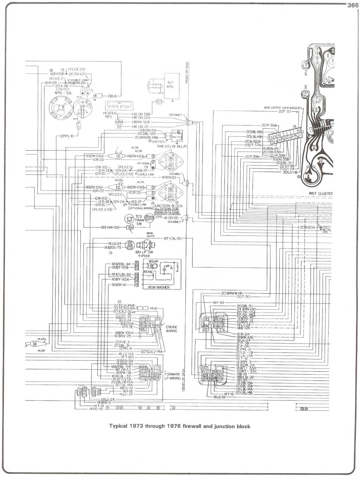
Wiring Layout for Early ’80s GM Pickup Electrical Panel
Start by locating the panel beneath the dash, on the driver’s side, just above the kick panel. Remove the plastic cover to access the terminals.
The top-left slot typically handles the headlamp circuit. Directly below, expect connections for tail lights and parking lamps. The upper-middle section usually links to the ignition switch and turn signals. Watch for a 20-amp rating on these slots.
Accessory power, including the radio and cigarette lighter, is often routed through the lower-right portion. These circuits are commonly protected by 25-amp elements. Heater blower motors use a separate slot in the lower-left corner, often with a 30-amp protector.
Labeling inside the lid is minimal or worn out on many units, so verify each line with a test light or multimeter before replacing elements. Always disconnect the battery to avoid shorts during inspection or replacement.
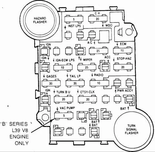
Fuse Locations and Labeling in the 1981 Chevy Truck Under-Dash Panel

Begin by removing the lower dashboard trim on the driver’s side to access the panel. The layout features two vertical columns with labeled slots arranged from top to bottom.
Top left position: Marked for STOP-HAZ, protects brake light and hazard circuits (20A).
Second from top left: PWR ACC, linked to accessory ports like the cigarette lighter (20A).
Middle left row: TAIL-CTSY slot, governs tail lamps and dome light (20A).
Bottom left corner: INST LPS, tied to gauge backlighting (5A). This is usually dimmable via the headlight switch.
Top right side: WIPER slot, assigned to windshield motor controls (25A).
Second right from top: TURN-B/U, supplies current to signal indicators and reverse lights (20A).
Lower right row: HEATER, powering blower motor circuits (25A).
Bottom right corner: RADIO slot, dedicated to audio unit and antenna power (10A).
Each cavity is clearly etched or printed with abbreviations. If labels are worn, refer to the service manual or look for embossed letters in the black plastic frame. Always match amperage ratings when replacing elements to avoid circuit damage.
Common Electrical Issues Related to the 1981 Fuse Box Layout

Start by checking the terminals for corrosion, especially near the accessory and ignition circuits. Green or white residue on connectors often causes voltage drops and intermittent failures.
Replace any 20-amp slot that feeds the blower motor if the fan works only on high speed. This typically indicates a failing resistor or poor contact in the relay circuit.
For headlights dimming unexpectedly, inspect the wiring behind the panel labeled for exterior lighting. Loose connections or partially melted plastic around spade connectors can signal overheating.
If the tail lights or brake lights don’t respond to pedal input, inspect the contact points tied to the brake switch. In many cases, overheating deforms the retaining clips, causing inconsistent contact.
When the horn or cigarette lighter fails, test the continuity across the accessory power splices. Heat damage or brittle insulation in this area is a known cause of short circuits.
For gauges that flicker or stay pegged, look closely at the feed line tied to the instrument cluster. Oxidation or arcing at the tab connection is common and should be cleaned or replaced.
Check for shared grounds near the mounting bracket if multiple systems act erratically. Poor grounding in this area disrupts current flow and mimics deeper wiring faults.
How to Safely Replace Fuses in a 1981 Chevy Truck
Disconnect the battery before touching any electrical components to prevent shorts or accidental shocks.
- Locate the panel under the dashboard on the driver’s side. Use a flashlight to clearly see the slots and labels.
- Use a plastic puller or insulated tweezers–never metal tools–to remove the damaged unit.
- Match the amperage rating printed on the blown piece with the replacement. Common values include 5A, 10A, 20A, and 30A.
- Inspect the prongs for corrosion. Clean the contact points with electrical contact cleaner if necessary.
- Firmly insert the new component into the correct slot without forcing it. Misalignment may damage the socket.
Always keep spares in the glove compartment and label each with its rating for quick access during breakdowns.