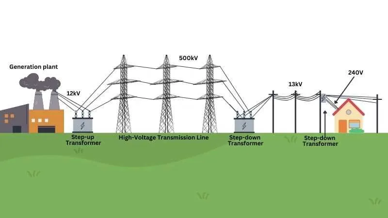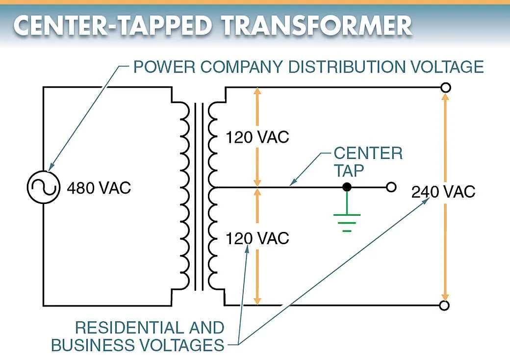
Start by identifying the primary and secondary coil terminals accurately to ensure proper linkage within the power system. Use a delta or wye configuration depending on load requirements and system grounding preferences. Each connection style affects voltage balance and current flow differently.
When arranging the leads, maintain correct polarity and phase sequence to avoid malfunction or damage to equipment. Confirm that the interconnection follows standardized labeling–usually marked as H1, H2, H3 on the input side and X1, X2, X3 on the output.
Incorporate proper insulation and spacing between conductors to prevent short circuits and reduce electromagnetic interference. Secure all terminals with torque-specified fasteners to guarantee stable operation under varying electrical loads.
Connection Layout for a 3-Element Electrical Transformer
Use a star (Y) or delta (Δ) configuration depending on load and system requirements. For a load requiring neutral, a star arrangement on the secondary side is preferred. In contrast, a delta connection suits systems needing high starting torque or balanced load distribution without neutral.
Primary Setup: Connect each input line to individual windings, ensuring proper insulation and secure terminals to prevent faults. Maintain consistent phase sequence to avoid voltage imbalance.
Secondary Configuration: Link output coils according to the desired voltage and current rating. Employ insulated busbars for easy maintenance and minimize losses by using short, thick conductors.
Grounding: Properly ground the neutral point if present to stabilize voltage and protect equipment. Use protective devices like circuit breakers and fuses on each output line.
Verify all connections with a continuity tester before energizing. Label terminals clearly to aid future troubleshooting and ensure compliance with electrical standards.
How to Identify Primary and Secondary Connections in Three Phase Transformers
Locate the nameplate data first. It provides voltage ratings, connection types, and terminal markings which distinguish input and output windings.
Primary terminals are usually marked with letters such as H1, H2, H3 or X1, X2, X3 depending on the manufacturer. Secondary terminals often have corresponding labels like X1, X2, X3 or Y1, Y2, Y3.
Check voltage levels: The higher voltage side represents the input coil, while the lower voltage side indicates the output coil. Use a multimeter to confirm rated voltages between terminals.
Observe terminal arrangements: Input connections tend to be grouped and clearly separated from output terminals. Wiring diagrams from the manufacturer often show the standard terminal layout.
Identify the connection style: Delta or wye configurations have distinct terminal patterns. For instance, a wye connection typically has a neutral point accessible on the secondary side, marked as N or neutral.
Use color coding and physical labeling: Insulation colors or tags may help differentiate input leads from output leads, especially in field installations.
Confirm polarity and phasing by performing phase rotation tests. This ensures correct identification and prevents misconnection in the system.
Step-by-Step Guide to Connecting Delta and Wye Configurations

For a delta connection, link each coil end to the start of the next coil, forming a closed loop. Ensure all junctions are secured with proper terminals to prevent loose contacts. Label each corner to match corresponding line inputs.
Begin by identifying the three sets of windings. Connect the end of winding A to the start of winding B, winding B end to winding C start, and winding C end back to winding A start. This creates the characteristic triangle layout with no neutral point.
For a wye setup, connect one end of each coil together to form a common neutral point. Use a solid bus bar or lug to gather these three ends firmly. The remaining free ends become the line terminals.
Verify that neutral connections are tight and insulated properly to avoid shorts. Attach the neutral conductor from this junction to the neutral bus if needed. Confirm continuity and insulation resistance before energizing.
Double-check the phasing sequence by using a phase rotation meter. Correct phasing ensures balanced loads and prevents equipment damage. Adjust terminal connections if the rotation is reversed.
Always follow manufacturer markings and color codes for identification. Record terminal assignments and secure all connections with torque-controlled tools. Use insulated tools and observe safety precautions during the entire process.
Troubleshooting Common Connection Errors in Triphasic Units
Verify polarity and sequence before energizing equipment to prevent phase displacement and circulating currents.
- Check each conductor for correct terminal placement according to the unit’s schematic.
- Measure continuity and resistance values on each winding to detect open circuits or shorts.
- Confirm neutral connections are secure and grounded properly to avoid unbalanced loads.
- Inspect for swapped line leads causing reverse rotation or improper load sharing.
- Use a phase rotation meter to verify correct sequence and avoid malfunction in downstream devices.
Follow these steps to isolate and fix typical misconnection issues:
- Disconnect power and label all cables clearly.
- Compare actual terminals with manufacturer’s connection chart.
- Correct mismatched leads, ensuring adherence to vector group specifications.
- Retest insulation resistance to confirm absence of damage after adjustments.
- Apply voltage gradually and monitor for abnormal temperature rise or vibration.
Common faults like reversed phases, neutral dislocation, and improper tap changer links cause operational failures and reduce equipment lifespan. Regular audits with precision tools minimize downtime and maintenance costs.