
When it comes to wiring a 5 pin rocker switch, it is essential to have a clear understanding of how the switch works and how to properly wire it. The Nilight 5 pin rocker switch is a versatile switch that can be used for a variety of applications, including controlling LED lights, fog lights, and other electrical devices.
Before we dive into the wiring diagram for the Nilight 5 pin rocker switch, let’s take a look at how the switch operates. The switch has five terminals: two for power, two for the accessory or device that the switch will control, and one for the ground connection. It features a lighted rocker switch with a built-in LED that illuminates when the switch is turned on.
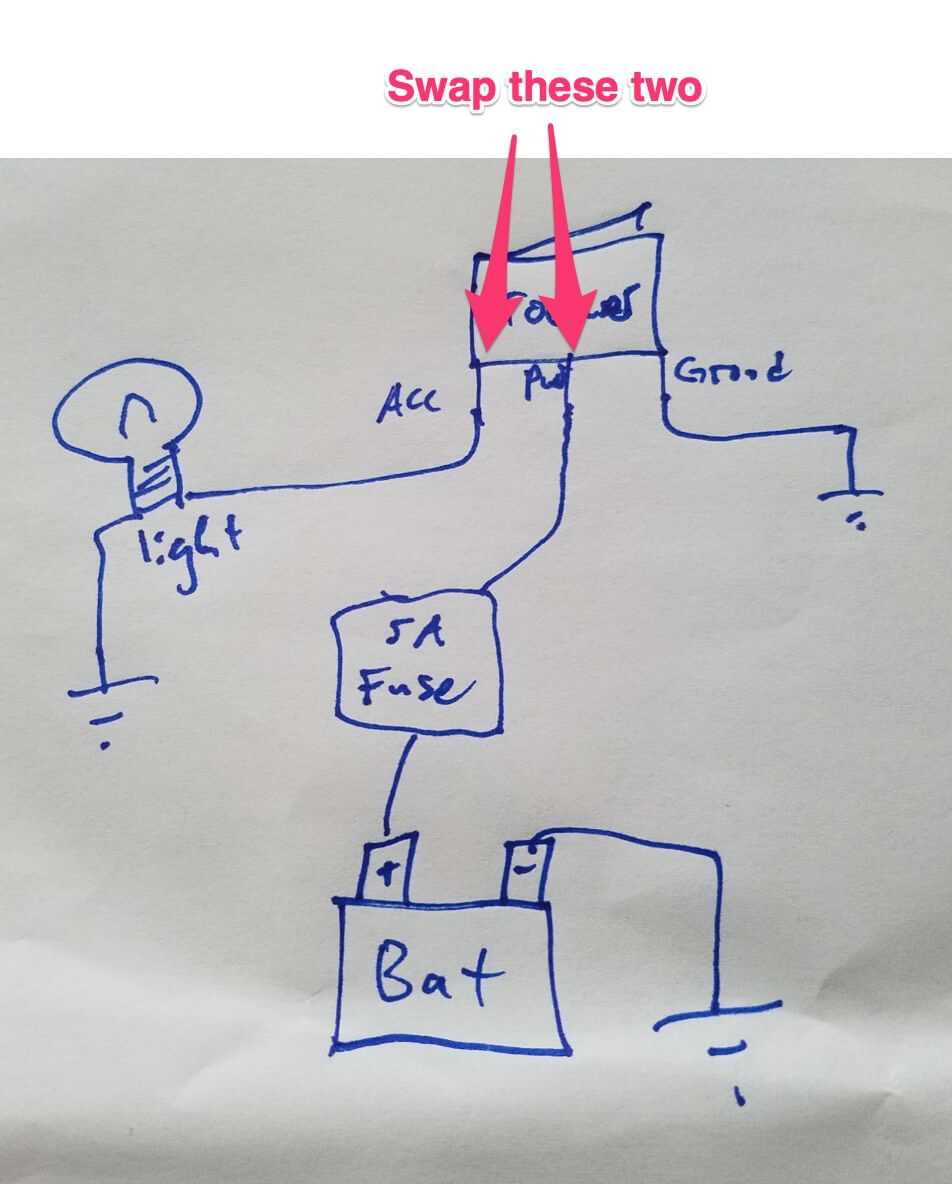
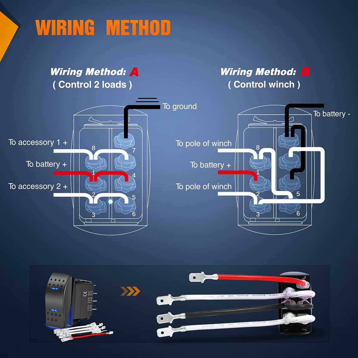
Now, let’s move on to the wiring diagram for the Nilight 5 pin rocker switch. It is important to follow the correct wiring diagram to ensure the switch functions properly and to prevent any electrical issues. The wiring diagram will show the connection points for the power, accessory, and ground terminals, as well as any additional components that may be required for your specific application.
Understanding the Basics of Nilight 5 Pin Rocker Switch Wiring Diagram
When it comes to wiring a Nilight 5 pin rocker switch, it is important to understand the basics of the wiring diagram. The wiring diagram provides a visual representation of the electrical connections and components involved in the switch. By understanding this diagram, you can properly wire the switch for your specific application.
The Nilight 5 pin rocker switch typically consists of five pins, labeled 1, 2, 3, 4, and 5. Each pin has a specific function and should be connected accordingly. Pin 1 is usually the power input, pin 2 is the load output, pin 3 is the ground, pin 4 is the accessory power, and pin 5 is used for the backlighting (if applicable).
To properly wire the Nilight 5 pin rocker switch, you will need some basic tools and materials including electrical wire, a soldering iron, solder, heat shrink tubing, and a wire stripper. Begin by identifying the pins on the switch and their corresponding functions. Then, cut the electrical wire to the appropriate length and strip the ends.
Once the wire is prepared, solder the appropriate wires to each pin of the switch according to the wiring diagram. Use heat shrink tubing to insulate and protect the soldered connections. It is important to ensure that the wires are securely and properly connected to their respective pins to avoid any electrical issues.
If the Nilight 5 pin rocker switch has backlighting, you will also need to connect the appropriate wires to pin 5 for the backlighting to function properly. This may require an additional power source for the backlighting circuit.
After the wiring is complete, it is important to test the switch to ensure proper functionality. Apply power to the switch and verify that it operates as intended, activating the load when switched on and deactivating it when switched off.
Understanding the basics of the Nilight 5 pin rocker switch wiring diagram is crucial for proper installation and functionality. Taking the time to carefully study the diagram, properly connect the wires, and test the switch will ensure a successful and safe wiring process.
What is a Nilight 5 Pin Rocker Switch?
A Nilight 5 Pin Rocker Switch is an electrical switch that is commonly used in automotive applications. It is a type of switch that has five pins or terminals, which allows it to control the operation of different electrical accessories in a vehicle.
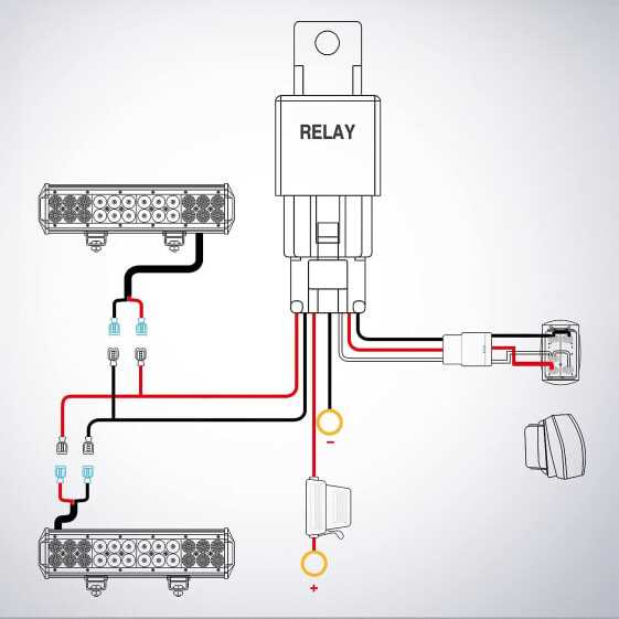
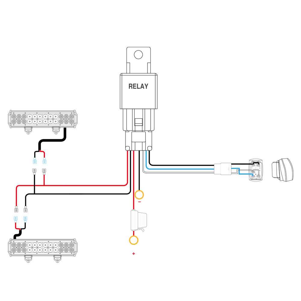
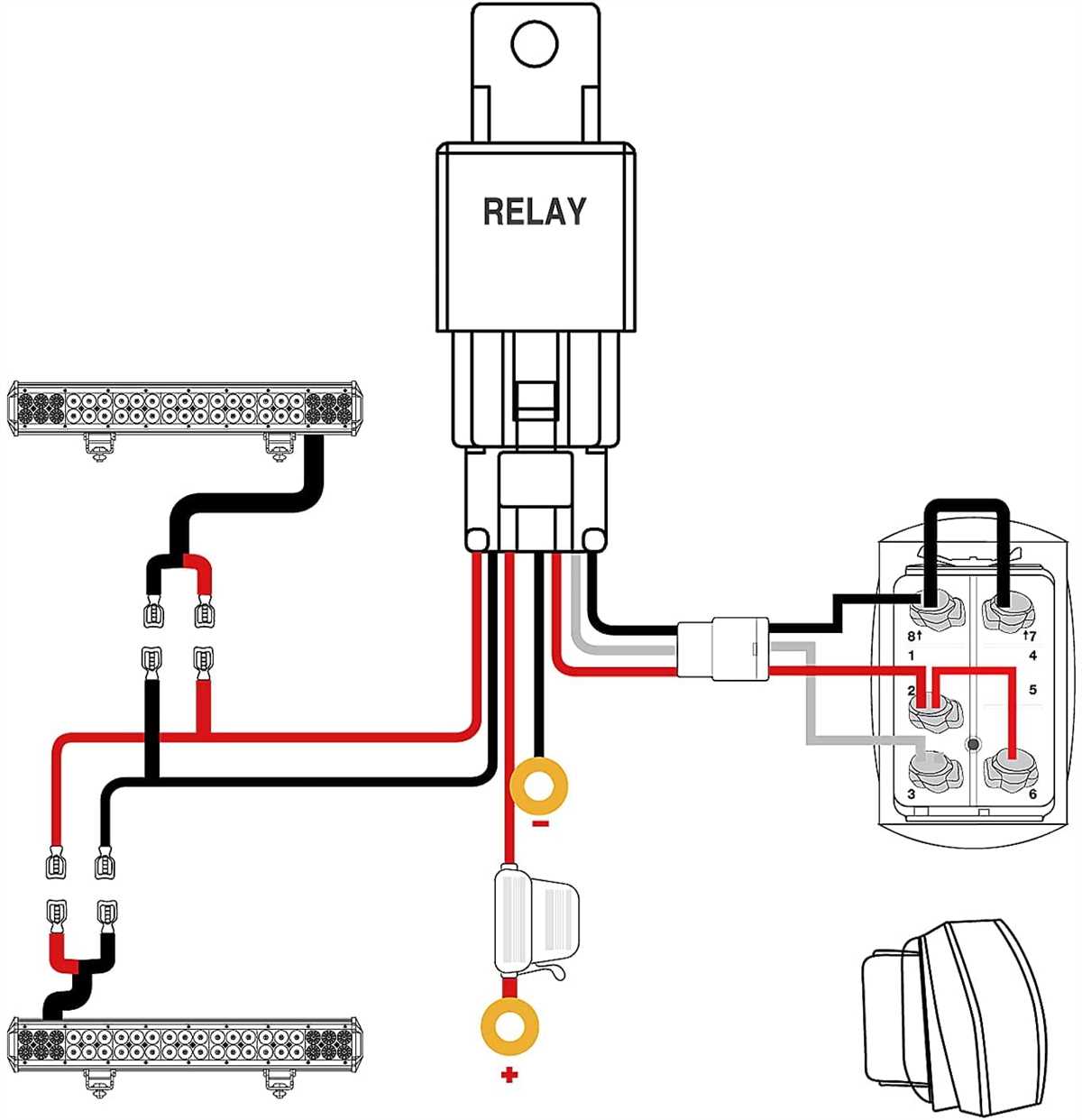
The Nilight 5 Pin Rocker Switch is designed to fit into a standard rocker switch mounting hole, making it easy to install in most vehicles. It is commonly used to control various functions such as lights, winches, fog lights, and other accessories.
The five pins on the switch are labeled and serve different purposes. The first pin is for power, the second and third pins are for the accessory that the switch controls, and the remaining two pins are for the illuminated backlight of the switch. These pins are usually marked or color-coded for easy identification and proper wiring.
The wiring diagram for a Nilight 5 Pin Rocker Switch may vary depending on the specific model and application. It is important to refer to the manufacturer’s instructions or diagram to ensure proper installation and wiring of the switch.
Overall, the Nilight 5 Pin Rocker Switch is a versatile and reliable switch that allows easy control of various electrical accessories in a vehicle. Its compact design and ease of installation make it a popular choice among automotive enthusiasts.
Components of a Nilight 5 Pin Rocker Switch Wiring Diagram
A Nilight 5 pin rocker switch wiring diagram outlines the various components and connections needed to properly wire the switch in a circuit. This diagram is essential for understanding how to correctly install and connect the switch, ensuring it functions as intended.
Here are the key components typically found in a Nilight 5 pin rocker switch wiring diagram:
- Switch: The main component of the wiring diagram is the rocker switch itself. It is a mechanical device that is used to control the flow of electricity in the circuit. It has five pins, each serving a specific purpose in the wiring configuration.
- Power Source: The power source is where the electrical current originates. It could be a battery, fuse box, or any other source of power in the circuit. The wiring diagram will indicate how the power source should be connected to the switch.
- Load: The load refers to the device or component that the switch controls. It could be something like a light, fan, or any other electrical device. The wiring diagram will show how the load should be connected to the switch.
- Ground: The ground is an important connection that ensures the safety and proper functioning of the circuit. It provides a path for excess electrical current to flow in the event of a fault. The wiring diagram will indicate how the ground should be connected to the switch.
- Other Components: Depending on the specific application, there may be other components included in the wiring diagram, such as resistors, capacitors, or diodes. These components are added to the circuit to achieve specific functions or protect the switch and load.
When following a Nilight 5 pin rocker switch wiring diagram, it is important to pay attention to the specific pin assignments and connections described. Properly wiring the switch is crucial for the overall functionality and safety of the electrical circuit.
Pin Configurations and Functions
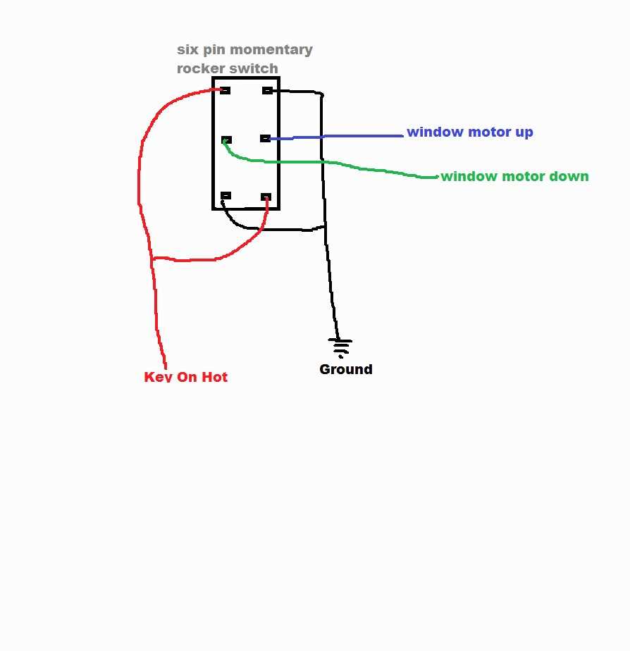
The Nilight 5-pin rocker switch has five pins, each with its own specific function. Understanding the pin configurations and their functions is essential for proper wiring and usage of the switch.
Pins 1 and 2: These pins are connected to the load, such as a light or any other electrical device that needs to be controlled. Pin 1 is the positive (+) terminal, while pin 2 is the negative (-) terminal. The load should be connected accordingly to ensure proper functionality.
Pin 3: Pin 3 is the power input terminal and should be connected to a suitable power source. This can be the positive terminal of the battery or any other power supply. It is important to ensure that the power source is appropriate for the load and switch rating.
Pin 4: Pin 4 is the power output terminal and is used to connect the switch to the load. This pin is connected to pin 2 when the switch is in the ON position, allowing power to flow from the power source to the load. When the switch is in the OFF position, pin 4 is disconnected from pin 2, cutting off the power supply to the load.
Pin 5: Pin 5 is the illumination control terminal. It is optional and is used to connect an indicator light, such as an LED, to indicate the status of the switch. This pin is usually connected to the positive (+) terminal of the indicator light, and the negative (-) terminal can be connected to a suitable ground source.
- Pin 1: Load positive (+) terminal
- Pin 2: Load negative (-) terminal
- Pin 3: Power input terminal
- Pin 4: Power output terminal
- Pin 5: Illumination control terminal (optional)
By understanding the pin configurations and their functions, you can confidently wire the Nilight 5-pin rocker switch to control your desired device or load while also utilizing the optional illumination feature, if applicable.
Wiring the Power Source
When wiring the Nilight 5 pin rocker switch, it is important to first properly connect the power source. The power source can be a battery or any other source of electrical power. Here is a step-by-step guide on how to wire the power source:
Step 1: Identify the positive and negative terminals
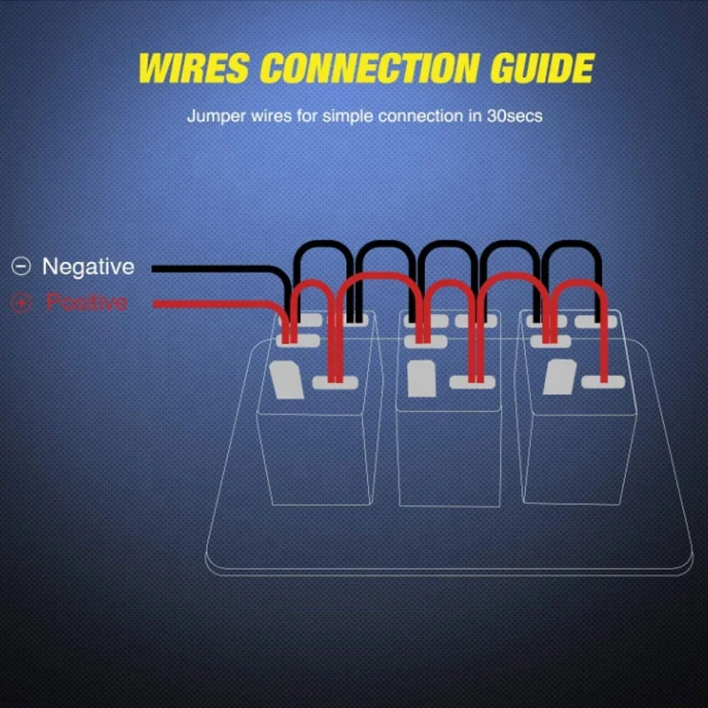
Before connecting the power source, it is crucial to identify the positive and negative terminals. The positive terminal is usually marked with a “+” sign or a red color indicator, while the negative terminal is marked with a “-” sign or a black color indicator.
Step 2: Connect the positive terminal
Start by connecting the positive terminal of the power source to the corresponding terminal on the rocker switch. Use appropriate connectors, such as ring terminals or butt connectors, to ensure a secure and reliable connection. Make sure to tighten the connection properly to avoid any loose connections.
Step 3: Connect the negative terminal
Next, connect the negative terminal of the power source to a suitable ground point. This can be a metal surface or a designated ground point on a vehicle. Again, use appropriate connectors to ensure a secure connection. It is important to have a solid ground connection to ensure the switch functions correctly.
By properly wiring the power source, you can ensure that the Nilight 5 pin rocker switch operates efficiently and reliably.
Connecting the Load
Connecting the load to the Nilight 5 pin rocker switch is a straightforward process. The switch has five pins labeled with numbers or letters indicating their function. These pins are typically labeled 1, 2, 3, 4, and 5.
Pin 2 is the output, and this is where the load will be connected. The load can be any electrical component or device that you want to control with the switch, such as a light bar or fog lights. Make sure to properly size the load according to the switch’s specifications to avoid any electrical issues.
Once you have identified Pin 2, you can connect the positive wire of the load to it. This can be done by either soldering the wire to the pin or using a crimp connector. Make sure to secure the connection properly to ensure a reliable electrical connection.
If you are using the switch to control an LED light bar, you may also need to connect the negative wire of the load to a suitable ground connection. This will complete the circuit and allow the switch to control the power to the load.
Remember to refer to the wiring diagram provided with the Nilight 5 pin rocker switch for specific instructions and guidelines. It is essential to follow the correct wiring procedures to ensure a safe and functional installation of the switch and connected load.
Step-by-Step Guide to Wiring a Nilight 5 Pin Rocker Switch
In this guide, we will walk you through the process of wiring a Nilight 5 pin rocker switch. This switch is commonly used in automotive and marine applications to control various electrical devices. By following these steps, you’ll be able to successfully wire the switch and use it to control your desired equipment.
What You’ll Need:
- Nilight 5 pin rocker switch
- Wire cutters/strippers
- Electrical tape
- Electrical connectors (such as butt connectors or crimp connectors)
- Electrical wires
- A power source
- The equipment you want to control
Step 1: Understanding the Pin Layout
Before starting the wiring process, it’s important to understand the pin layout of the Nilight 5 pin rocker switch. This switch typically has five pins labeled 1, 2, 3, 4, and 5. Pin 2 and Pin 5 are usually the power input and output pins, while Pins 1, 3, and 4 are used as the control pins.
Step 2: Prepare the Wires
Using your wire cutters or strippers, prepare the wires that will be connected to the switch. Strip about a 1/4 inch of insulation from the ends of the wires to expose the bare copper.
Step 3: Connect the Wires
Now it’s time to connect the wires to the switch. Connect the positive power wire to Pin 2 and the negative wire to Pin 5. Use the appropriate electrical connectors to secure the connections. Make sure the connections are tight and secure.
Next, connect the wires from your equipment to the control pins. The specific pin configuration will depend on the function you want the switch to control. Consult the wiring diagram provided with your equipment or refer to the Nilight 5 pin rocker switch wiring diagram for guidance.
Step 4: Test the Connection
Once all the wires are connected, it’s important to test the connection before finalizing the installation. Connect the power source and turn on the switch to check if it properly controls the equipment. If everything works as intended, proceed to the next step.
Step 5: Secure the Wiring
After testing, secure the wiring by using electrical tape or any other suitable methods. Make sure the wires are neatly organized and protected from any potential damage.
Following these steps will ensure a successful wiring of your Nilight 5 pin rocker switch. Always refer to the provided wiring diagram and follow any specific instructions for your equipment to ensure proper and safe operation.
Gathering the Necessary Tools and Materials
Before you start wiring the Nilight 5 pin rocker switch, it’s essential to gather all the necessary tools and materials to ensure a smooth and efficient installation process. Here’s a list of what you’ll need:
Tools:
- Wire crimpers: These will be used to crimp connectors onto the wires.
- Wire strippers: This tool will help you remove the insulation from the wires.
- Screwdriver: You may need a screwdriver to attach the switch to the surface.
- Electrical tape: Use electrical tape to secure the connections and prevent any short circuits.
- Multimeter: This tool will come in handy for testing the switch and ensuring proper connectivity.
Materials:
- Nilight 5 pin rocker switch: Make sure you have the correct switch for your specific wiring needs. Refer to the wiring diagram to determine the appropriate switch.
- Wire: You’ll need the appropriate gauge and length of wire for your specific application.
- Connectors: Choose connectors that are compatible with your wires and switch.
- Fuse holder and fuse: If your switch requires a fuse, make sure you have the appropriate fuse holder and fuse to protect your circuit.
- Mounting hardware: Depending on where you’re installing the switch, you may need screws or adhesive to secure it to the desired surface.
By gathering all the necessary tools and materials before starting the installation, you’ll save time and ensure that you have everything you need to complete the wiring process efficiently.