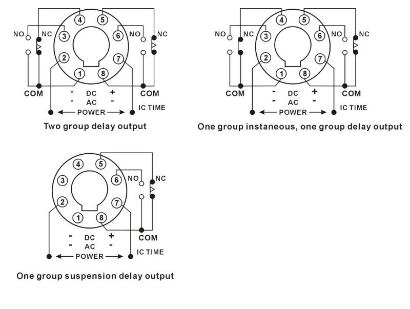
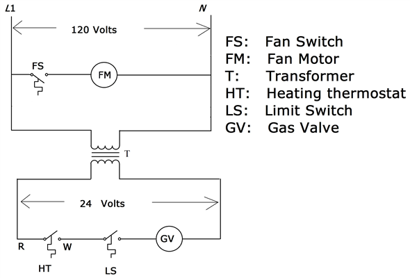
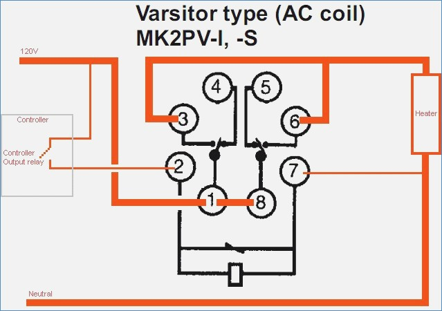
In the schematic diagrams, each thick line indicates the external wiring; shaded areas show internal connections. s H3CR-A .
s H3CR-A8 TWO-FUNCTION TIMER, DPDT CONTACT OUTPUT . Omron offers two types of time setting rings in.
schematron.org 1. (c)Copyright OMRON .
VDC power supply are available (the H3CR-A and H3CR-A).) 4. .
Block Diagrams. H3CR-A/ AS.
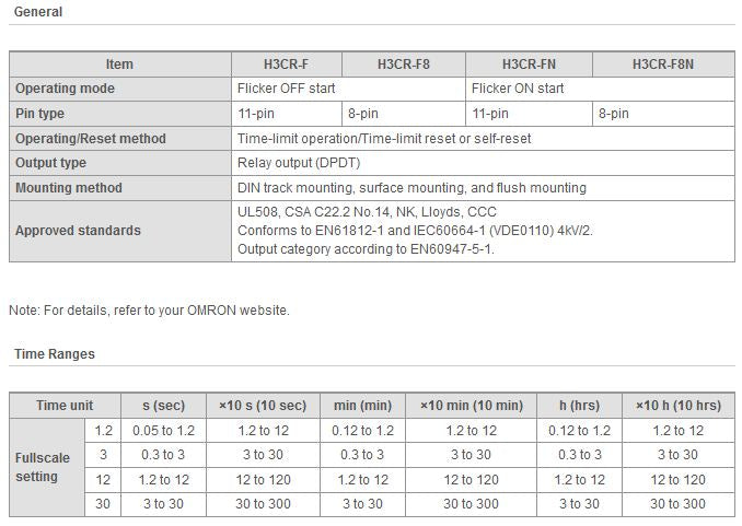
Item, H3CR-A/-AS/-A, H3CR-AP, H3CR-A8/-A8S/-A, H3CR-A8E. Operating mode, A: ON-delay.
B: Flicker OFF start. B2: Flicker ON start.
C: Signal . SOURCE: I use Omron H3CR 8pin. I don’t have exact schematic for your 8-pin timer.
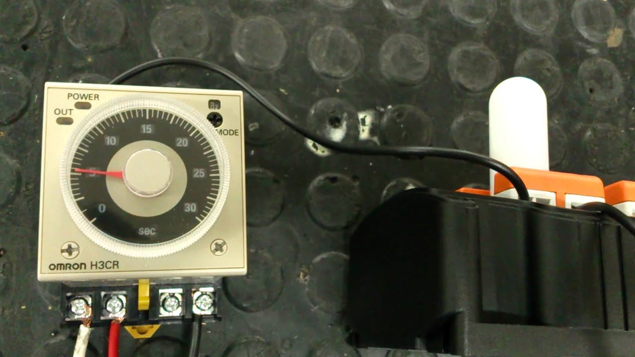
Use multimeter read ohms and voltage from pin socket to. Socket (H3CR-A8E, to VAC, to VDC).
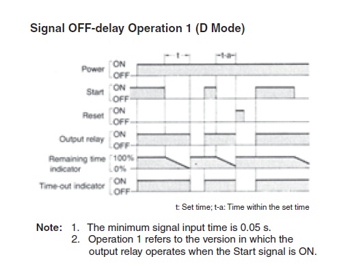
• PNP input .. Block Diagrams ..
terminals of those Timers must be wired properly so that they will not.Terminals 2 and 7 are the same as for the H3CR-A8. H3CR-A8E (Contact Output) Power supply Note: Terminals 1, 3, 4, and 8 are empty.
Terminals 2, 5, 6, 7, and 10 are the same as for the H3CR-A. H3CR-AP (Contact Output) Power supply Power supply Note: 1. Please note some product models not sold in Singapore may be included in the following manual(s) for our global customers. *It is recommended to select “Save” .
Solid-state Timer H3CR Solid-state Timer H3CR DIN 48 x mm Multifunctional Timer Series • Conforms to EN and IEC 4 kV/2 for Low Voltage, and EMC Directives. In the schematic diagrams, each thick line indicates the external wiring; shaded areas show internal connections.
H3CR-A, H3CR-AS (SIX-FUNCTION TIMERS) Mode A ON-Delay Signal Start/Signal Reset Power is applied continuously. Timing starts at the leading edge of the start input.
The output relay is energized when the. co tact out ut R.
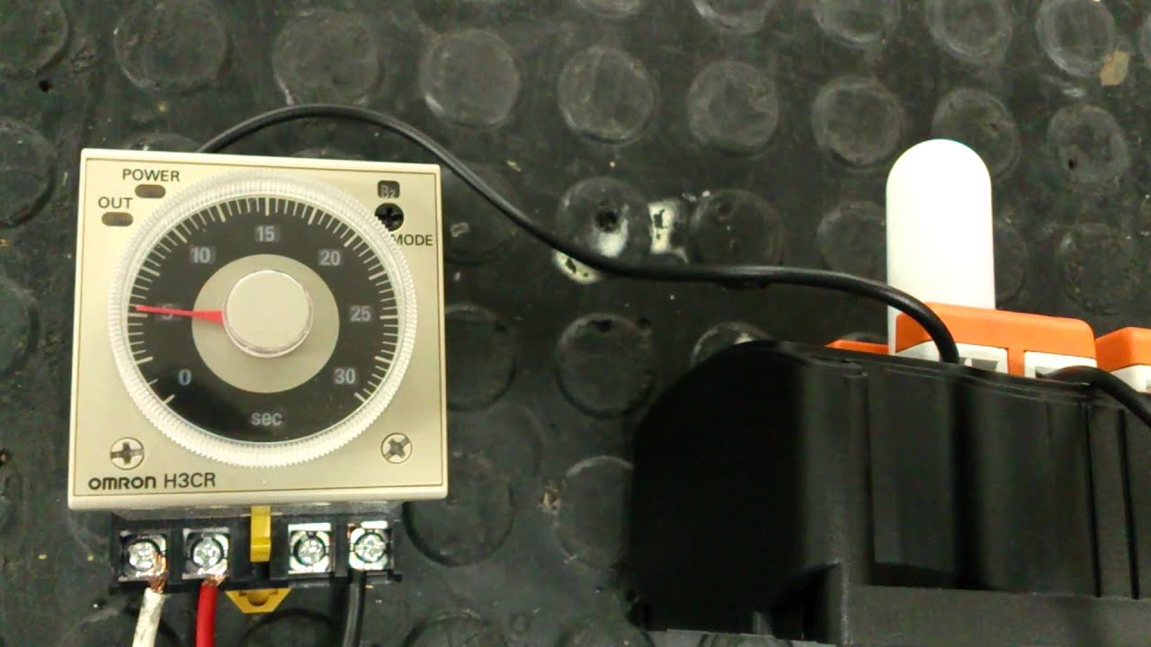
Solid-State Timer. H3CR-A.
1/16 DIN Analog-Set Timer with Many Time Ranges, Operating Modes and Wide Supply Voltage Range. H.
Field-selectable time ranges from Omron Timer Wiring – Detailed Wiring DiagramsH3CR-A Solid-state Multi-functional Timers/Manual | OMRON Industrial Automation Singapore