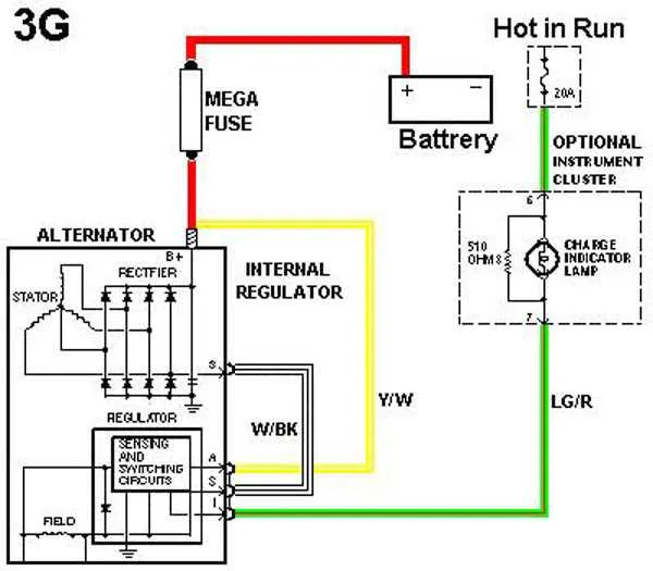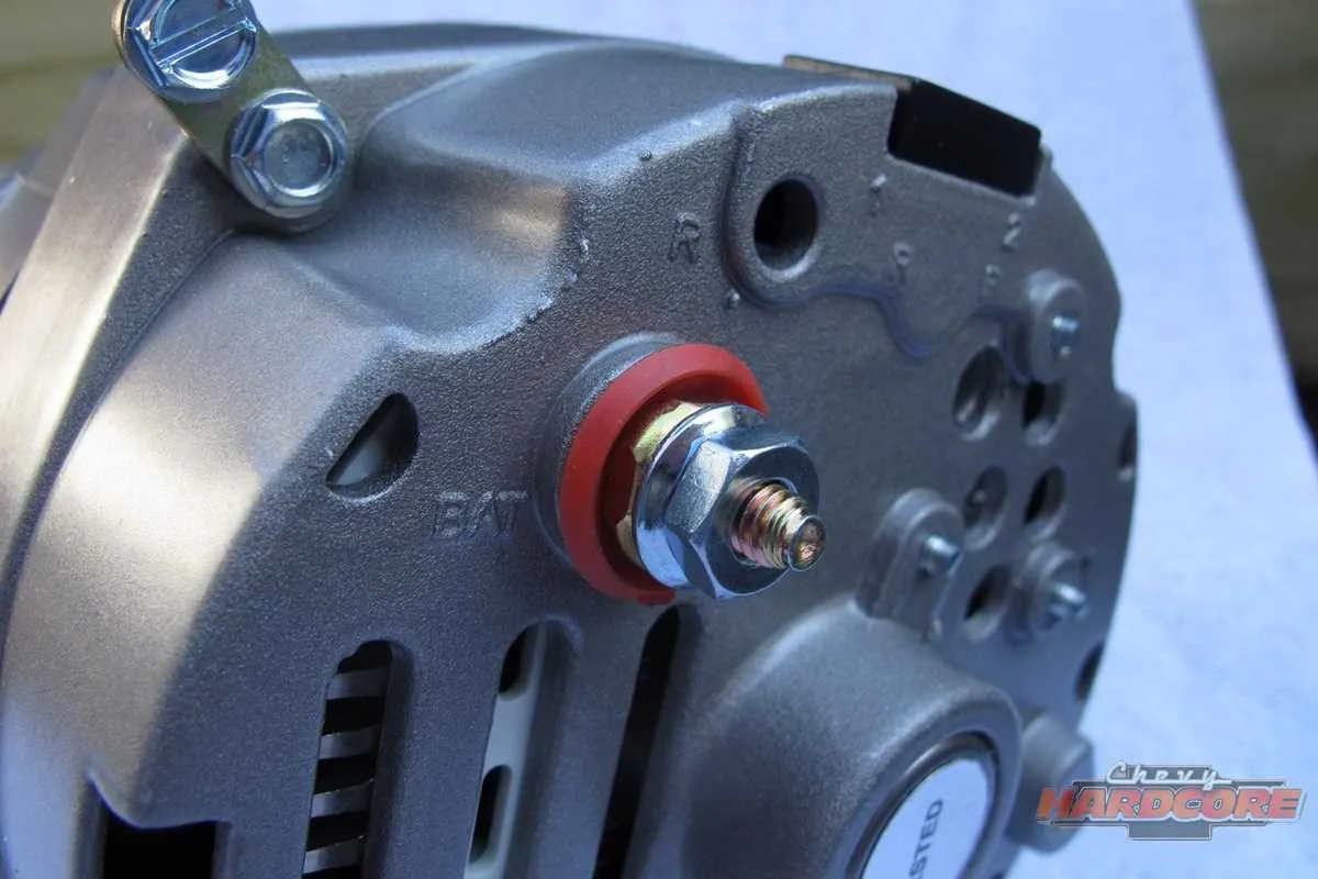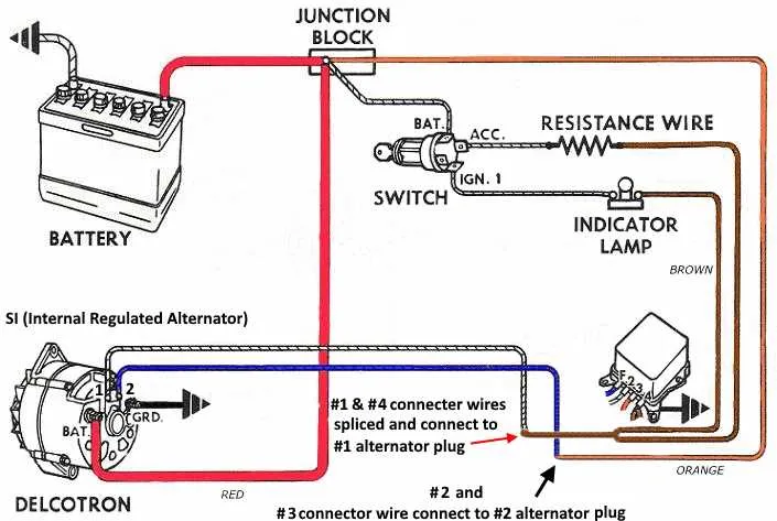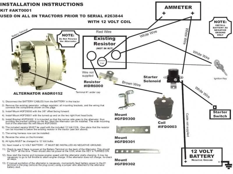
Connect the output terminal directly to the battery positive post using a thick-gauge conductor rated for high current flow. This ensures a stable charge cycle and eliminates the need for additional control modules.
Use a fused link close to the power source to prevent circuit damage in case of short faults. A 10-gauge copper line with a 100-amp inline fuse is a reliable configuration for most standard installations.
Grounding is critical: attach the unit’s casing to a clean, unpainted metal surface on the engine block or chassis. Secure contact prevents erratic voltage readings and improves system stability.
Bypass ignition triggers by selecting a model that self-excites above idle speed. This simplifies layout and removes the need for external energizing circuits.
Route the conductor away from moving parts and high-heat zones. Use corrugated tubing or heat-resistant sleeves where necessary to maintain insulation integrity and reduce wear over time.
Efficient Setup for Single-Cable Power Unit

Connect the positive terminal directly to the battery via a heavy-gauge conductor, ideally 4 AWG or thicker, to handle high current flow without voltage drop. Avoid inline fuses; instead, route through a properly rated circuit breaker near the energy source.
Secure the housing to a solid ground point on the engine block using a clean, corrosion-free surface. A dedicated ground strap enhances system stability, especially in older vehicles with inconsistent grounding.
Ensure the output stud connects cleanly to the distribution point or starter solenoid terminal. Minimize cable length to reduce resistance. Use high-quality crimp connectors and heat-shrink tubing to prevent moisture intrusion.
After installation, verify voltage at idle reaches 13.8 to 14.5 volts using a multimeter. If output is low, inspect for grounding issues or insufficient cable gauge. For vehicles with high-demand electronics, consider adding a capacitor or voltage stabilizer inline.
How to Connect a Single-Cable Charging Unit to a Classic Car

Mount the charging device securely using factory brackets or custom mounts ensuring full belt alignment. Use a V-belt with correct tension–approximately ½ inch of play at midpoint between pulleys.
Attach a 10 AWG or thicker insulated conductor directly from the output terminal to the positive side of the battery or to the main terminal on the starter solenoid, depending on vehicle configuration. This line must be protected with a 100-150 amp inline fuse or fusible link within 12 inches of the connection point.
Ensure proper grounding by connecting a heavy-gauge conductor (minimum 10 AWG) from the housing to the chassis. Clean all surfaces of paint, rust, or debris to ensure metal-to-metal contact.
| Connection | Location | Cable Gauge | Protection |
|---|---|---|---|
| Output Terminal | Battery Positive or Starter Post | 10 AWG or thicker | 100-150 Amp Fuse |
| Ground | Unit Case to Frame | 10 AWG or thicker | None (Direct Ground) |
Start the engine and use a multimeter to verify voltage at battery terminals–expect a steady reading between 13.8 and 14.5 volts. If voltage remains unchanged, inspect all contacts and ensure a solid chassis ground is established.
Steps to Ensure Proper Grounding in a One Wire Setup
Secure a clean, corrosion-free contact point on the engine block using a star washer under the ground terminal for solid conductivity.
- Use a braided strap or heavy-gauge cable (minimum 4 AWG) to connect the housing directly to the engine ground.
- Ensure the paint, rust, and oil are fully removed at all contact surfaces before attaching the grounding lug.
- Run an additional strap from the engine to the chassis to complete the return path and minimize voltage drop.
- Verify continuity with a multimeter between the power unit’s case and battery negative terminal; resistance should read near zero ohms.
- Install star washers between terminals and metal surfaces to penetrate coatings and improve metal-to-metal contact.
- Re-check connections after the first few hours of operation to ensure vibrations haven’t loosened the ground path.
Avoid using body panels or brackets as the primary return path–they may introduce unwanted resistance or cause erratic charging behavior.
Troubleshooting No-Charge Issues After Installation

Start by verifying battery voltage with a multimeter; it should read at least 12.4 volts before engine start and rise to 13.8–14.6 volts at idle if charging is active. If voltage stays low, inspect the drive belt for proper tension and signs of slipping or glazing.
Next, confirm that the output terminal has a solid connection to the positive battery post. Corrosion, loose terminals, or undersized cables can cause voltage drop and prevent current flow. Use a voltage drop test across the positive and ground paths under load.
Check the housing’s ground path to the engine block. A poor ground–often due to paint or rust–interrupts circuit continuity. Clean all mounting points to bare metal and use a continuity tester to confirm less than 0.1 ohms resistance.
If equipped with an internal regulator, verify that engine RPM exceeds the minimum self-excitation threshold, typically around 1200 RPM. Revving the motor briefly can trigger the system to begin output. If this fails, internal excitation components may be defective.
Inspect for a parasitic drain or short that may trigger system protection. Disconnect the unit and test current draw with the ignition off. Any reading above 50 milliamps may indicate a wiring fault or damaged diode trio.
Finally, test field coil resistance across the internal terminals if accessible; values outside 2–5 ohms usually signal an open or shorted winding. Replace the unit if readings are abnormal and other diagnostics are inconclusive.