If you’re troubleshooting your snow removal machine, it’s essential to focus on the key components of its power setup. Ensuring proper connections and understanding the flow of electricity through the system can prevent malfunctions and improve performance during heavy use. Start by checking the fuse box and the main controller for any signs of wear or damage.
Identify the main wiring harness, which connects the control unit to the hydraulic system. This harness often carries the signals that control the lift and angle functions. Make sure each wire is securely attached, with no exposed metal, to avoid short circuits.
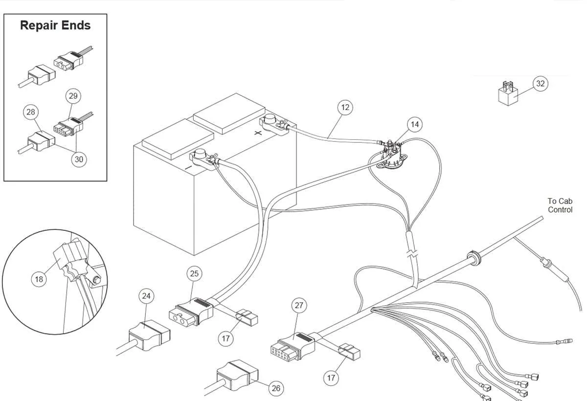
Examine the relay and solenoid connections, as these are critical for proper power distribution to the motors. Look for any signs of corrosion or loose connections, which could lead to intermittent failures. Proper maintenance of these parts ensures that the motor operates efficiently, even in extreme temperatures.
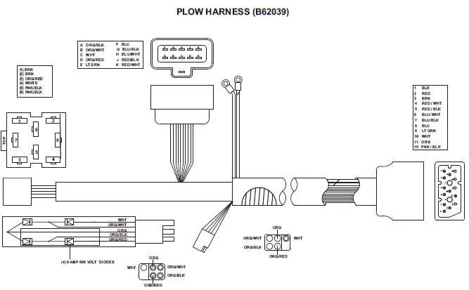
Finally, always consult the manufacturer’s wiring guide if you’re unsure about the configuration. The layout of the electrical components may differ slightly depending on the model, so cross-checking against the recommended diagram is crucial to avoid incorrect wiring that could compromise the safety and functionality of the equipment.
Understanding the Wiring System
For optimal operation, it’s essential to correctly wire the snow removal equipment. Follow these specific steps to ensure everything is connected properly:
- Power Source Connection: Ensure the vehicle’s power outlet is functioning before making any electrical connections. A faulty battery or power source can lead to system malfunctions.
- Relay Configuration: Check the relay connections closely. Each relay should correspond to a specific function, like controlling the lifting mechanism or angling function. Verify each relay pinout matches the manufacturer’s wiring guide.
- Grounding: Proper grounding is critical for avoiding electrical interference. The ground wire must be securely attached to a clean, unpainted metal surface on the vehicle frame.
- Fuse Size and Placement: Use fuses that match the power requirements. A fuse that’s too small will blow prematurely, while one that’s too large could lead to equipment damage during short circuits.
- Control Switch Wiring: The controller should be wired to activate all essential components like lifting, angling, and lowering the blade. Ensure the switch’s wiring is free from damage or wear.
To troubleshoot issues, start by inspecting all wiring for wear or fraying. If a function isn’t operating, verify that the relay connections are intact and that the ground wire is properly secured. Regular inspection of the fuse system and control switches can prevent unexpected failures.
Understanding Key Components of the Diagram
The first step in analyzing the wiring schematic is to focus on the control unit, which acts as the brain of the system. This component regulates power distribution and signals to various other elements, such as the motor and switches. Pay close attention to the input and output pins, ensuring all connections are correctly established to avoid malfunctions.
Next, the actuator connections must be checked. These typically include solenoids that control the movement of mechanical parts. Verify that each solenoid is linked to the appropriate power source, and inspect the relay circuits that manage their operation. Inaccurate connections here can lead to unresponsive or erratic movement.
The circuit’s fuse block is another crucial area. Ensure that fuses match the specified ratings for each component to prevent overheating or short circuits. Incorrect fuse ratings can result in permanent damage to the system or a complete failure to operate.
Finally, check the grounding points. A solid ground connection is vital for maintaining stable operation and preventing electrical surges. The grounding wire should be tightly secured to a metal part of the frame to ensure proper functionality and safety.
Identifying Common Wiring Issues and Fixes

Check for Loose Connections: Inspect all terminals and connectors for tightness. Loose wires can cause intermittent power loss. Tighten or replace any connectors that appear corroded or damaged.
Inspect for Short Circuits: Look for signs of melted insulation or burn marks along cables. Shorts often occur where wires come into contact with metal surfaces or each other. Cut the power and replace any damaged wires.
Verify Fuse and Relay Functionality: A blown fuse or faulty relay can stop the system from operating properly. Test each fuse with a multimeter and replace any that are defective. Also, check relays for continuity and swap out any that are malfunctioning.
Examine Grounding Connections: A poor ground connection can result in erratic behavior or failure to function. Ensure that the ground wire is securely attached to a clean, corrosion-free surface.
Check for Corrosion: Corrosion at the connection points can increase resistance, leading to voltage drops. Clean any corroded terminals with a wire brush or contact cleaner, and replace any parts showing severe damage.
Test Continuity: Use a multimeter to check for continuity along the wires. Open circuits can be diagnosed by testing each wire segment, identifying the break, and repairing it by splicing or replacing the section.
Verify Proper Voltage: Ensure that the system is receiving the correct voltage at each connection point. Use a voltmeter to measure voltage at various points, comparing readings to the expected values in the manual.
How to Properly Interpret the Circuit Layout

Start by identifying the power source. Locate the primary input terminal on the layout and follow the main lines to ensure you understand the flow from the power source to the control components.
Next, observe the symbols used for switches, relays, and fuses. Each component is represented by a standardized symbol, so familiarize yourself with these to easily identify their function. For example, a simple switch is often represented as a break in the line, while a relay will have a distinctive coil and contact pattern.
Pay close attention to the wiring configuration. The arrangement of connections will indicate how the current flows between components. Use the line paths to trace how power moves through the system, activating various components in sequence or in parallel.
Examine the connections for ground points and circuit protection devices. Grounding ensures safety and proper operation by directing excess current to the earth. Circuit protection elements, such as fuses or circuit breakers, will interrupt the flow in case of overloads or faults.
For components with variable resistance or adjustment capabilities, ensure that the layout specifies control points or potentiometers. These adjustments allow for fine-tuning performance within the system.
Finally, note the orientation and placement of components relative to each other. The physical arrangement on the layout can reveal the order in which systems activate or deactivate, allowing for a clearer understanding of how the system operates as a whole.
| Component | Symbol | Function |
|---|---|---|
| Switch | — | Opens or closes the circuit, controlling current flow. |
| Relay | [Coil] (Contacts) |
Electromagnetic switch that controls other components based on input signals. |
| Fuse | –[F]– | Protects the circuit from overload by breaking the connection when current exceeds safe limits. |
| Ground | ⏚ | Directs excess current to the earth for safety purposes. |