We use the PI Diagram module from Autodesk.
This enables us to increase our efficiency, by extraction of the following lists: Pipe lists; Instrument lists; Valve lists . Dictionary:Pi diagram.
From SEG Wiki. Jump to: navigation, search.
Other languages: English • español · Pole diagram (q.v.). Retrieved from.
Download scientific diagram | PI diagram: impulsive, dynamic, and quasistatic loading. from publication: Design of Blast-Loaded Glazing Windows and Façades .
We use the PI Diagram module from Autodesk. This enables us to increase our efficiency, by extraction of the following lists: Pipe lists; Instrument lists; Valve lists .
Dictionary:Pi diagram. From SEG Wiki.
Jump to: navigation, search. Other languages: English • español · Pole diagram (q.v.).
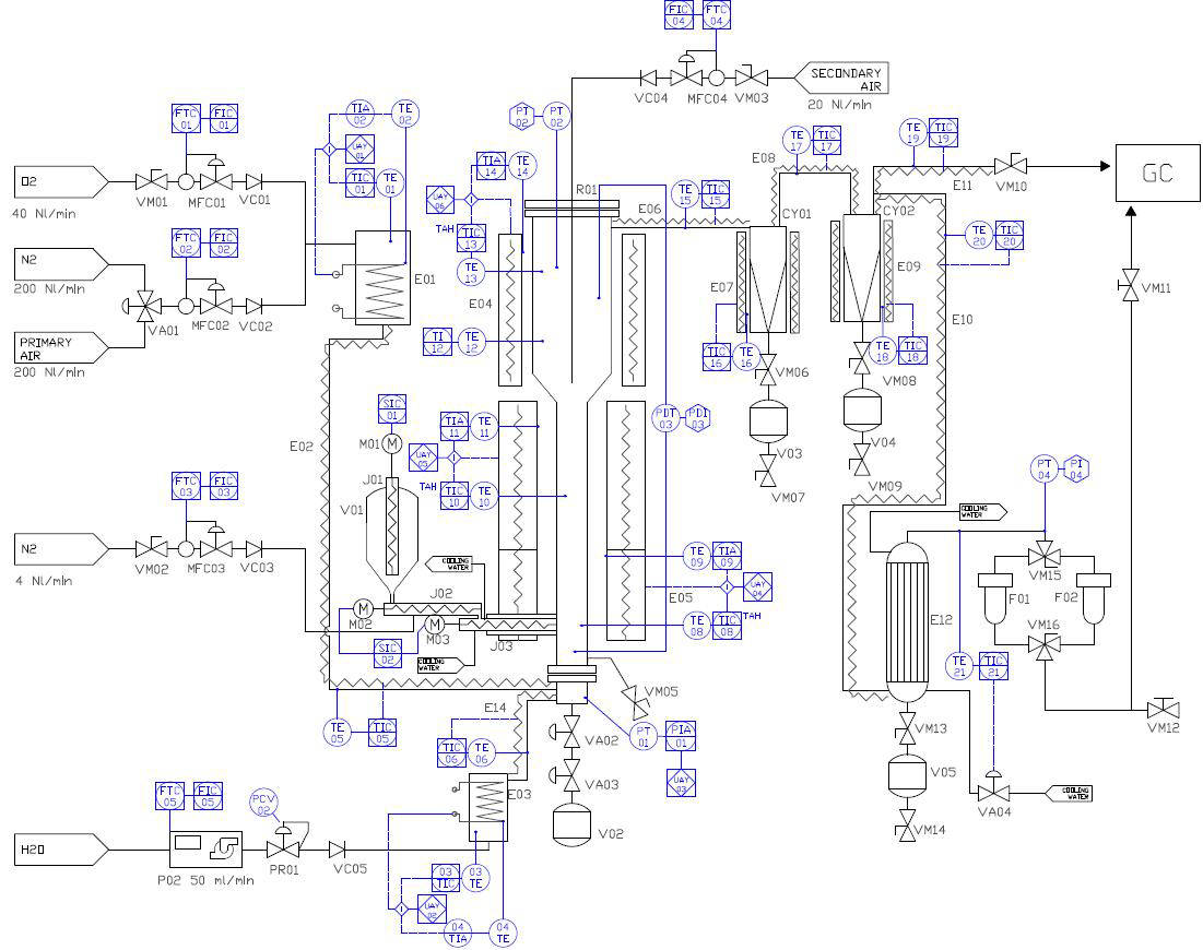
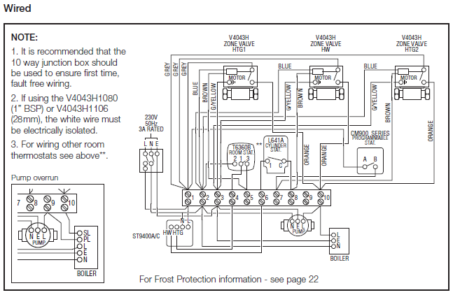
Retrieved from.P&IDs can seem mysterious, but don’t have to stay that way thanks to our intuitive P&ID schematron.org the what, why, and how of everything Piping & Instrumentation Diagrams in this comprehensive guide. A piping and instrumentation diagram (P&ID) is a detailed diagram in the process industry which shows the piping and vessels in the process flow, together with the instrumentation and control devices.
A piping and instrumentation diagram (P&ID) is defined by the Institute of Instrumentation and Control as follows: A diagram which shows the interconnection of process equipment and the instrumentation used to control the process. P&ID – Piping and Instrumentation Diagram P&ID is a schematic illustration of a functional relationship between piping, instrumentation and system components.
Sponsored Links. P&ID’s shows all piping including physical sequences of branches, reducers, valves, equipment.
(Adapted from Bruce G. Lovelace, “Piping and Instrument Diagrams”, handout given at seminar held at Michigan Technological University, Dept. of Chemical Engineering, November 5, ).PI-Diagram Design – Vertex Systems Oypi diagram | schematron.org
