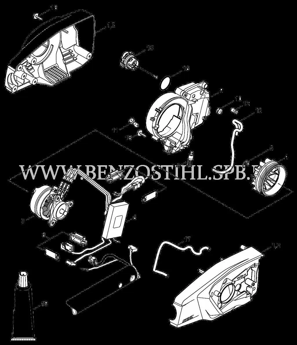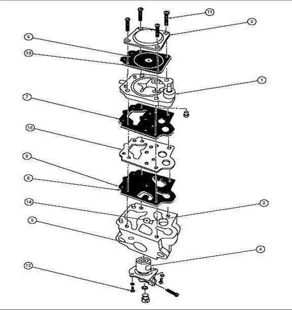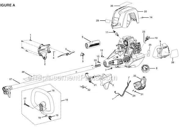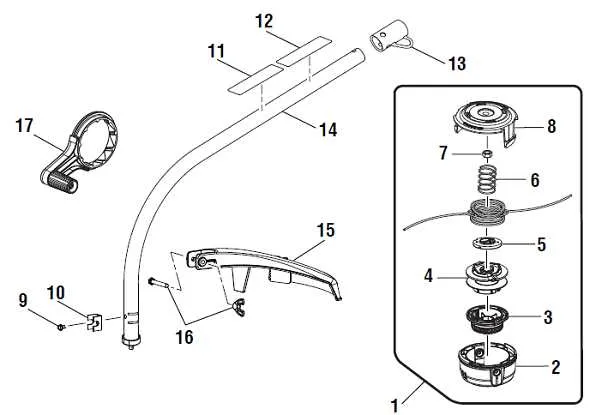
For optimal performance and easy repairs, it’s crucial to understand the specific arrangement of parts within the model S430. The guide below provides precise details about each crucial element and how they interconnect. Proper identification of these components ensures quick troubleshooting and avoids unnecessary part replacements.
First and foremost, identify the motor assembly, which is a key driver in the overall function. Pay close attention to the alignment of the drive shaft and its connection to other moving parts. Regular maintenance of this part can prevent system overloads and enhance the tool’s longevity.
Secondly, the carburetor and air filter must be inspected regularly. These parts are responsible for maintaining the fuel flow and preventing debris from entering the engine. Neglecting these components can lead to decreased performance or engine stalling.
Next, ensure that the gear mechanism is properly lubricated. This ensures smooth operation and reduces friction that can cause wear and tear. A lack of lubrication will likely result in the premature failure of internal gears.
Finally, always keep an eye on the casing and handle. A secure grip and sturdy housing are essential for user safety and the tool’s durability. Tighten any loose screws and replace worn-out handles promptly to avoid mishaps during use.
Detailed Breakdown of Key Components

The key components for this model include the engine, carburetor, recoil starter, and fuel tank assembly. Ensure the engine’s piston and cylinder remain well-lubricated to avoid overheating and enhance performance. Regular inspection of the carburetor is crucial; clean it every 25 hours of use to prevent clogging and ensure smooth operation.
For the recoil starter, check the spring and cord tension. If the pull cord is stiff or frayed, replace it immediately to avoid potential damage to the starter mechanism. Inspect the fuel tank for any signs of wear or leakage. It’s recommended to replace the fuel lines every 50 hours to avoid fuel contamination.
Pay close attention to the air filter. If it’s clogged, it reduces engine efficiency and could lead to overheating. A clogged filter should be cleaned every 10 hours of operation. The exhaust system should also be checked for blockages that could impact engine performance, and the muffler should be tightened periodically to prevent loose parts during use.
Inspect the ignition coil and spark plug regularly. A faulty ignition system can cause misfiring or prevent the engine from starting altogether. Ensure the spark plug is cleaned and replaced every 100 hours of use or whenever starting issues occur.
Finally, lubricate all moving parts, including the throttle lever, choke mechanism, and any pivot points in the frame. Proper maintenance of these elements ensures smooth operation and reduces wear over time.
Understanding the Major Components of the Machine

Start by identifying the critical elements that ensure proper functionality and performance. These essential components contribute significantly to the overall efficiency and lifespan of the device.
- Engine Unit – The heart of the system, providing the power necessary for operation. Regular checks for wear and lubrication are recommended to avoid overheating or performance degradation.
- Fuel Tank – Ensures uninterrupted operation by supplying the necessary energy. Ensure the fuel filter is clean and replace the tank if any cracks or damage are detected.
- Carburetor – Controls the air-to-fuel ratio, essential for optimal engine performance. Cleaning and proper adjustment are key to preventing engine stalling or poor starting.
- Air Filter – Protects the engine from dust and debris. A clogged filter can lead to decreased engine efficiency, so replace it regularly to ensure smooth operation.
- Throttle Mechanism – Regulates engine speed. A faulty throttle can cause erratic performance. Regular inspections for dirt buildup or damage are crucial.
- Drive Shaft – Transfers power from the engine to the operational components. Inspect for any signs of wear or rust, which can cause slipping or loss of power.
- Handle Assembly – Provides the user with a secure grip. Ensure that all screws are tightened and that no cracks are present in the structure to maintain safety and comfort.
Maintaining these components in optimal condition will ensure a reliable and efficient performance. Regular inspections, timely replacements, and proper handling can significantly extend the machine’s operational life.
Identifying Replacement Components in the S430 Schematic
Start by locating the engine housing section–this area typically includes the recoil starter, air filter cover, and spark plug boot. Reference numbers in this zone often begin with single digits or low teens.
Move to the fuel system area. Look for the fuel tank assembly, including the fuel lines, filter, and grommet. These elements are usually grouped under one cluster with sequential item codes. Pay close attention to hose routing and connector shapes.
Inspect the shaft assembly next. Focus on the flexible drive cable, coupler, and lower housing. Their identifiers are usually positioned midway through the schematic, sometimes starting in the 20s or 30s.
For clutch and gearbox components, locate the section near the power transmission path. Here you’ll find elements such as the clutch drum, spring, and retaining washers. These are typically placed adjacent to or directly following the drive cable entries.
Throttle and control triggers are shown in the upper handle area. Verify part codes against the throttle cable routing and switch layout. Look for specific callouts for trigger return springs and pivot points.
Always cross-reference each label with the matching number in the bill of materials section, if available, to confirm correct sizing, version compatibility, and fastener requirements.
Step-by-Step Guide to Assembling the S430 with Diagram Reference

Begin with attaching the crankcase cover to the engine block using the correct hex screws (M5 x 25 mm). Tighten them evenly in a cross pattern to prevent warping.
Insert the piston into the cylinder, making sure the ring gap aligns with the locating pin. Lubricate lightly with 2-cycle oil before insertion. Secure the connecting rod to the crankshaft with the designated cap and bolts.
Mount the carburetor gasket and reed valve assembly between the intake and the air/fuel unit. Use the illustrated layout to ensure the gasket orientation is correct to avoid vacuum leaks.
Slide the flywheel onto the shaft, aligning the key properly. Torque the nut to 35 Nm. Attach the ignition coil with a 0.30 mm air gap from the flywheel magnets, using a feeler gauge.
Fix the recoil starter housing using four pan head screws (M4 x 18 mm). Verify that the rope retracts smoothly before proceeding. Do not overtighten to avoid cracking the plastic housing.
Connect the muffler with the heat shield in place, securing it with two M6 bolts and locking washers. Position the gasket between the exhaust port and muffler flange without gaps.
Install the driveshaft by sliding it into the clutch drum until it clicks into place. Confirm alignment by rotating the shaft by hand to check engagement.
Attach the fuel tank to the mounting bracket with two self-tapping screws. Connect the fuel lines: the longer one to the return, the shorter to the carburetor inlet. Refer to the schematic for line routing.
Finally, secure the engine cover with the integrated primer bulb and throttle trigger assembly. Ensure the throttle cable is seated correctly in the lever slot and test the trigger movement before tightening all fasteners.