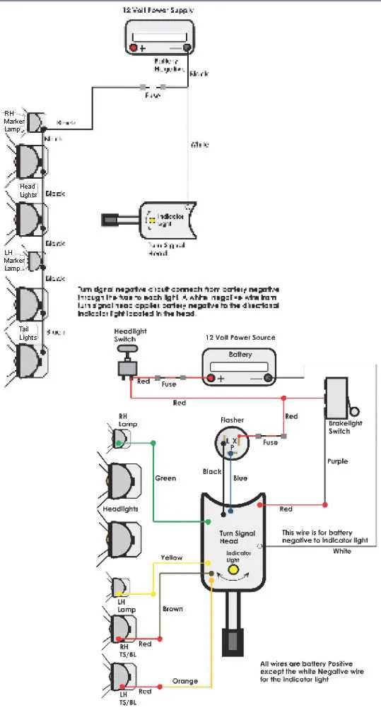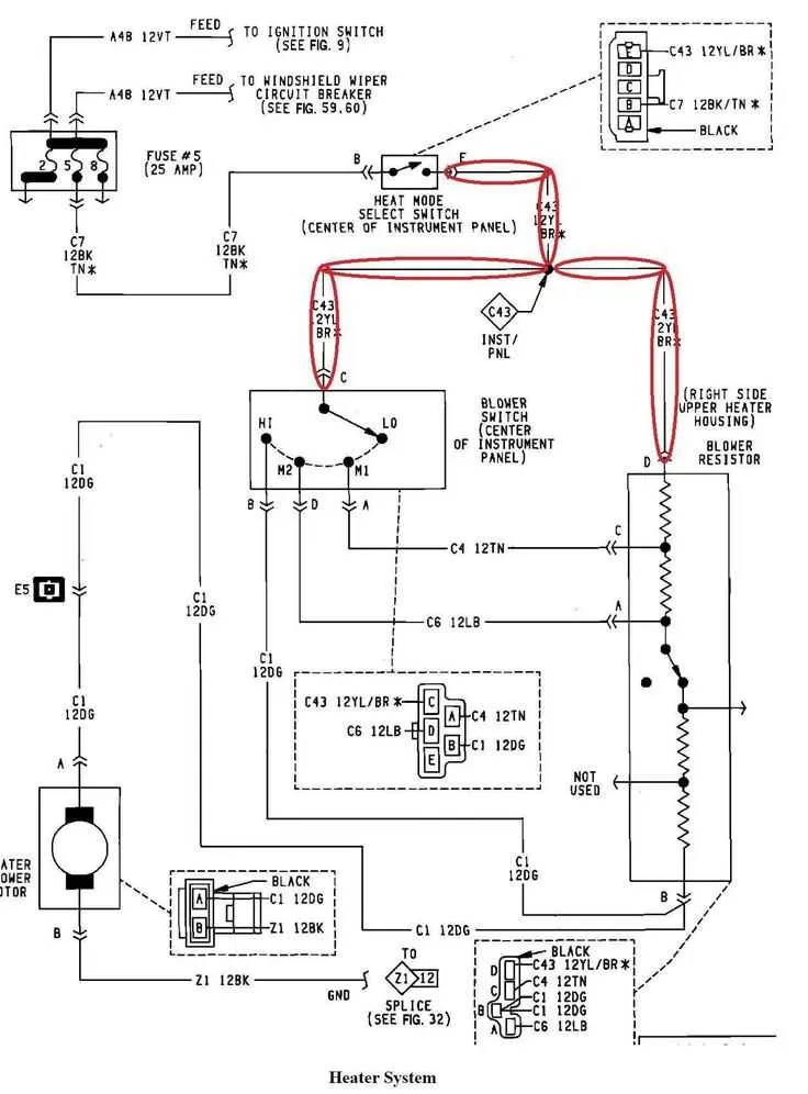
For an efficient and reliable power system, it is essential to understand the precise connections and components involved in a 36V E-Z-Go vehicle’s electrical system. To optimize performance and prevent frequent malfunctions, ensure that the battery pack is correctly wired with the proper polarity, and that each connection is securely tightened. When dealing with the control unit and motor, attention to the placement of each lead will drastically improve responsiveness and longevity of your vehicle.
Begin by confirming that the battery terminals are clean and free from corrosion. This small but crucial maintenance step ensures uninterrupted power flow. Once confirmed, focus on linking the main power leads from the battery pack to the controller. A proper connection here is critical, as it dictates the vehicle’s response time and power efficiency during operation.
For optimal functionality, pay special attention to the connections from the motor. Any loose or poorly connected wiring can lead to significant performance issues, such as weak acceleration or erratic behavior. It’s highly recommended to use high-quality connectors and terminals to avoid unnecessary wear and tear that might affect overall system performance. Additionally, ensure that the fuse is rated correctly for the system’s specifications to avoid potential overcurrent situations that could damage sensitive components.
Lastly, regularly inspect all wires and connections for any signs of wear, fraying, or short-circuiting. Using durable and insulated materials will extend the life of the system, reducing the frequency of repairs. Following these best practices ensures that your vehicle remains in peak condition, providing both safety and optimal performance.
36V EZ Go Electric Vehicle Electrical Layout

For troubleshooting or enhancing the electrical system of a 36V EZ Go model, it’s crucial to follow the layout of the power distribution and connections carefully. Start by ensuring that the main battery pack is correctly wired to the controller, providing consistent power flow. Double-check that each cell in the battery pack is connected in series to deliver the desired output.
The motor should be connected to the controller, which regulates the energy flow based on throttle input. Confirm that the throttle sensor is properly wired to the controller to ensure smooth acceleration. The solenoid acts as a switch that connects or disconnects the power from the batteries to the motor; make sure this component functions correctly to prevent any loss of power.
Each ground connection must be clean and secure, particularly between the battery and the motor. Weak or dirty grounds can lead to inefficient power use, or even complete system failure. Pay attention to the fuses and circuit breakers to avoid overloading and to protect the system from potential damage.
For the ignition system, ensure the key switch is wired to the controller and solenoid, allowing for proper power on/off functionality. The forward/reverse switch should also be checked for correct alignment and wiring to ensure smooth direction changes.
Test each connection with a multimeter to ensure that all components are receiving the correct voltage. Regularly inspect for loose connections, frayed wires, or any signs of wear to maintain optimal performance.
Understanding the Power System in a 36 Volt EZ Go Vehicle
To ensure optimal performance, it’s crucial to understand how the electrical components in a 36-volt EZ Go vehicle work together. The power source consists of six 6-volt batteries connected in series. This configuration provides the required energy to drive the motor and operate various electrical systems.
- Batteries: Six 6-volt batteries form the primary energy storage. The batteries must be charged regularly and checked for corrosion or leaks. Proper maintenance extends their lifespan and ensures the vehicle operates efficiently.
- Battery Connections: Inspect all connections for tightness and cleanliness. Loose or corroded connections can lead to voltage drops, affecting overall performance. Use a wire brush to clean terminals and apply anti-corrosion gel to prevent buildup.
- Controller: The controller regulates power flow from the batteries to the motor. It adjusts the speed and torque based on input from the accelerator pedal. A malfunctioning controller can cause erratic behavior or no power output at all.
- Motor: The motor is powered directly by the electrical system. Regularly check for signs of wear, such as unusual noises or overheating. Ensure the motor’s brushes are in good condition for smooth operation.
- Throttle: The throttle input determines the motor’s speed and responsiveness. Ensure that the accelerator is free from dirt and obstruction, and test it for consistent power delivery when pressed.
Periodic checks of these components ensure reliable and efficient energy transfer. Pay attention to the voltage levels in each battery to avoid undercharging or overcharging, which can damage the power storage. For best results, follow the manufacturer’s guidelines on charging and maintenance intervals.
Common Electrical Issues and Troubleshooting in 36V Systems
Corroded connections are a frequent cause of power loss. Inspect battery terminals, connectors, and cables for signs of rust or dirt buildup. Clean these areas using a wire brush and apply anti-corrosion grease to prevent further damage. Make sure connections are tight and free of any resistance-inducing debris.
Faulty battery packs can lead to inconsistent power delivery. Check each individual cell within the pack for uneven charge levels or leaks. A multimeter can help detect underperforming batteries. If one or more cells are significantly weaker, replacing the entire pack may be necessary.
Loose or broken fuses can stop the entire system from functioning. Ensure all fuses are intact and properly rated for the circuit. Replace any blown fuses with ones of the same amperage to avoid overloading the system.
Overheating motors may occur if the motor is overloaded or there’s an issue with the controller. Ensure that the motor isn’t obstructed by debris and check for smooth movement. Overheating could also indicate a need to clean or replace the motor brushes, or that the controller’s settings need adjusting to prevent excessive strain.
Controller failure is often due to short-circuits, faulty wiring, or power surges. Inspect all connections to the controller for wear or damage. If the controller’s display or functions are unresponsive, replacing it might be the only solution. Before replacement, confirm that the issue isn’t coming from a different component.
Inconsistent power output can stem from a defective relay or solenoid. Test the solenoid by bypassing it with a jumper wire to see if the system powers up. If this resolves the issue, replacing the solenoid is the next step.
Damaged cables can lead to intermittent power or no power at all. Look for any visible cuts, kinks, or fraying along the entire length of the cable. If any damage is found, cut and replace the damaged sections with high-quality, properly rated wire.
Unstable or flickering lights may indicate grounding issues. Check the ground connections between the battery, motor, and controller. A poor or loose ground connection can cause unstable voltage and erratic performance.
Step-by-Step Guide to Rewiring Your EZ Go Electric Vehicle

Begin by disconnecting the main power source to avoid any accidental electrical shorts. Ensure the battery is fully disconnected and all power is off before proceeding.
Remove any panels or covers that obstruct access to the internal components, such as the motor, controller, and battery compartment. Carefully label each wire as you disconnect them to simplify the reassembly process.
Check all connections for signs of wear or corrosion. Replace any damaged parts such as terminals, connectors, or wires. It’s crucial to use high-quality components to ensure the longevity of the system.
Starting with the motor, connect the positive and negative terminals to the designated motor terminals. Tighten the screws securely to avoid loose connections which could cause electrical issues later.
Next, connect the power controller to the battery pack. Ensure each connection is snug and properly insulated to prevent accidental shorts. Be mindful of the polarity when connecting to the controller and check the manufacturer’s instructions for specific requirements.
Reconnect the auxiliary power supply to any additional components, such as lights or horns, ensuring each accessory has its own dedicated circuit for safety.
Once all connections are made, double-check that no wires are pinched or exposed to the frame. Test the system by briefly powering up to confirm everything is working as expected. If necessary, adjust connections or replace any faulty components.
Finally, securely fasten any covers or panels and clean the area to remove any debris. Test the vehicle thoroughly to ensure optimal performance and safety.